
Wind-proof door body

A door body and door panel technology, which is applied in the field of windproof doors, can solve problems affecting people's normal living, etc., and achieve the effects of simple structure, convenient operation, and reduced adverse effects.

Active Publication Date: 2020-01-07
ZHEJIANG SHENGNA INTELLIGENT TECH CO LTD
View PDF5 Cites 1 Cited by
  • Summary
  • Abstract
  • Description
  • Claims
  • Application Information

AI Technical Summary

Problems solved by technology

[0003] The purpose of the present invention is to solve the problem in the prior art that the door is easy to move under the wind blowing and affect people's normal daily life, and proposes a windproof door body

Method used


Image

  • Wind-proof door body
  • Wind-proof door body
  • Wind-proof door body

Examples


Embodiment 1

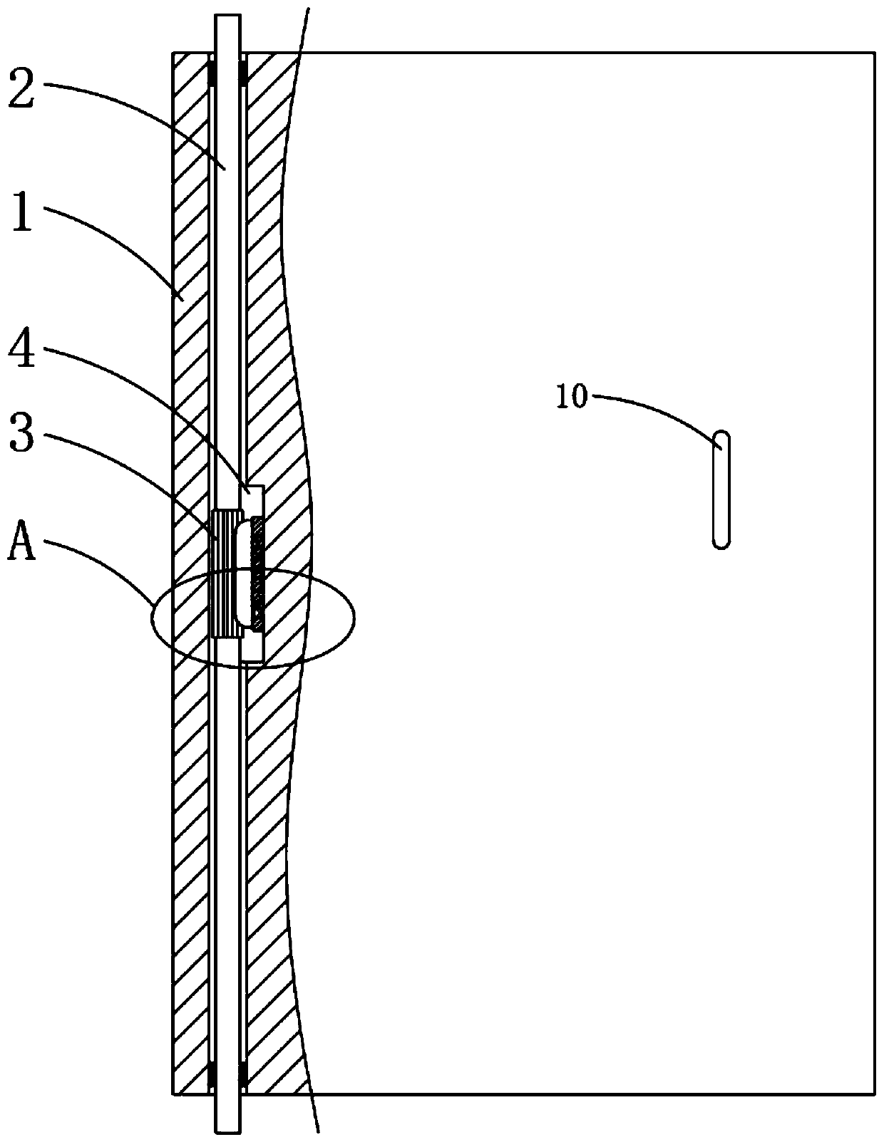
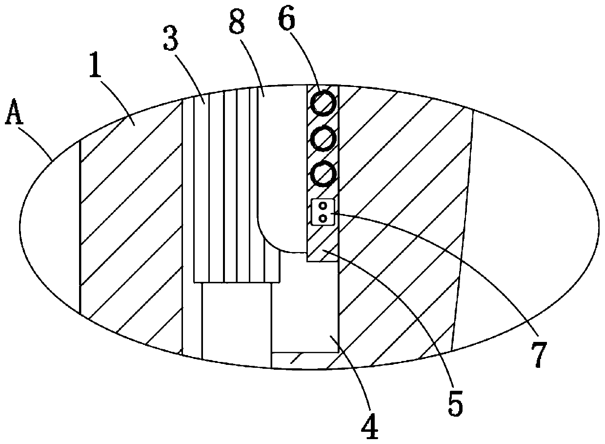
[0024] refer to Figure 1-5 , a windproof door body, including a door panel 1 and a door shaft 2, a through hole is opened on one side of the door panel 1, the door shaft 2 runs through the through hole and is rotationally connected with the door panel 1 using a bearing, and the door shaft 2 is fixed on the outside door frame A handle 10 is fixedly connected to the side of the door panel 1 away from the door shaft 2, a groove 4 is provided in the middle of the through hole, and a gear rod 3 is fixedly sleeved in the middle of the door shaft 2, and the cross section of the gear rod 3 is a spur gear-like structure. A rubber block 5 is glued and fixed in the groove 4. The rubber block 5 is embedded with multiple coils 6 and a first storage battery 7. The multiple coils 6 and the first storage battery 7 are connected in series to form a magnetic branch circuit. The rubber block 5 is close to the gear bar. One side of 3 is sealed and glued with a soft bag 8, which is filled with ma...

Embodiment 2

[0031] refer to Figure 6-8 , the difference between this embodiment and Embodiment 1 is that a control cavity 11 is provided on the part of the door panel 1 close to the handle 10, and two second connection posts 12 are fixedly connected in the control cavity 11, and the two second connection posts 12 pass through The air is electrically isolated, and the two second connecting columns 12 are electrically connected to the two ends of the magnetic branch circuit respectively. An electromagnet 15 is fixedly connected to the inner wall of the control chamber 11, and the electromagnet 15 is connected to the two second connecting columns. A second conductive sheet 14 is arranged between the 12, and the second conductive sheet 14 is made of ferrous material that can be attracted by a magnet. The side of the second conductive sheet 14 away from the electromagnet 15 is fixedly connected with a contraction spring 13. The spring 13 is fixed on the inner wall of the control cavity 11, an...


PUM


Abstract

The invention discloses a wind-proof door body. The wind-proof door body comprises a door plate and a door shaft, wherein a through hole is formed in one side of the door plate; the door shaft penetrates through the through hole and is rotatably connected with the door plate through a bearing; the door shaft is fixed on an external door frame; a handle is fixedly connected to one side, far away from the door shaft, of the door plate; a groove is formed in the middle of the through hole; a toothed bar is fixedly sleeved in the middle of the door shaft; the section of the toothed bar is of a straight gear-shaped structure; a rubber block is fixedly glued in the groove; a plurality of coils and a first storage battery are embedded in the rubber block; and the coils and the first storage battery are connected in series to form a magnetism generating branch. The wind-proof door body has the advantages that the toothed bar part structure is provided, when the door plate does not need to be rotated, the magnetism generating branch generates a magnetic field to enable a soft bag to be tightly meshed with the toothed bar, so that the door plate cannot rotate, the door plate is prevented from rotating under the action of wind when the door plate does not need to rotate, and the adverse effect of wind blowing on the life of people is greatly reduced.

Description

technical field [0001] The invention relates to the technical field of interior decoration, in particular to a windproof door body. Background technique [0002] The design of the room pays attention to a certain ventilation effect, and each room has ventilated doors and windows; when the airflow passes by, the indoor air is blown and renewed, but when the wind is too strong, the door is often closed or opened with the airflow; especially in cold In winter, the doors and windows of the bedroom are blown open by the wind, and the cold air from the outside rushes in, which will take away the heat in the room; at the same time, under the blowing of the wind, the door hits the door frame back and forth, making a "dong dong" noise , affect people's normal daily life and rest, and also cause certain damage to the door body; in addition, sometimes the door body may be closed by the wind force when going out for a short time, and the user is locked out of the door with embarrassment...

Claims


Application Information

Patent Timeline
IPC IPC(8): E06B3/36E06B3/70E05D7/081E05D11/10E05B1/00
CPCE05B1/0015E05D7/081E05D11/1028E06B3/36E06B3/70
Inventor 顾海明
Owner ZHEJIANG SHENGNA INTELLIGENT TECH CO LTD
Learn More