
Method for diagnosis and/or maintenance of a brake of a transportation system, software program, and brake apparatus

A brake and brake control technology, which is applied in the direction of brake type, mechanical equipment, circuit breaker test, etc., can solve problems such as multiple reaction times, and achieve the effect of maintaining continuous operation

Pending Publication Date: 2020-01-07
KONE CORP
View PDF7 Cites 1 Cited by
  • Summary
  • Abstract
  • Description
  • Claims
  • Application Information

AI Technical Summary

Problems solved by technology

In situations where a lower braking torque is required, the reaction time of the brake limits the spring force adjustment to this braking torque, since low spring force results in excessive reaction time

Method used


Image

  • Method for diagnosis and/or maintenance of a brake of a transportation system, software program, and brake apparatus
  • Method for diagnosis and/or maintenance of a brake of a transportation system, software program, and brake apparatus
  • Method for diagnosis and/or maintenance of a brake of a transportation system, software program, and brake apparatus

Examples


Embodiment Construction

[0065] Now, an exemplary embodiment of the present invention will be described in more detail.

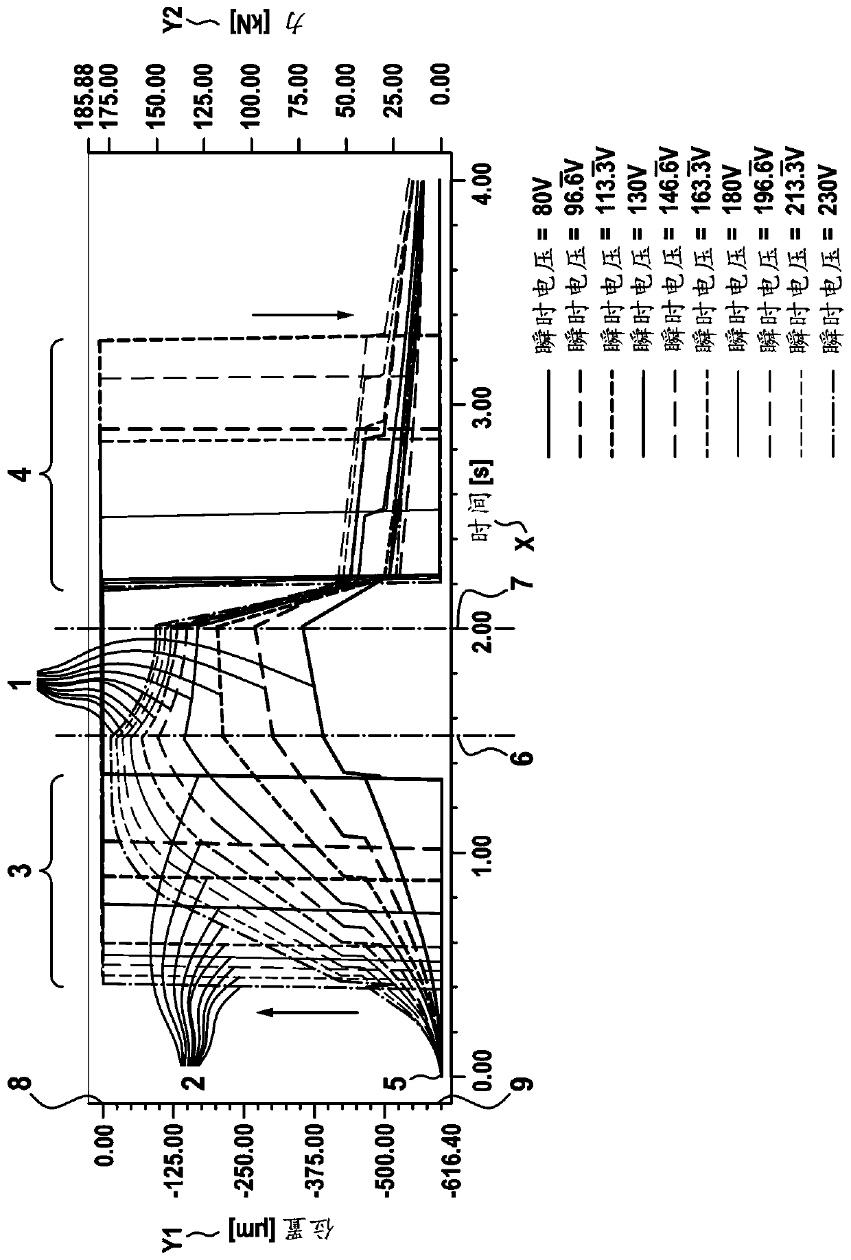
[0066] figure 1 The results of the transient FEM analysis of the brake operation according to the present invention are shown. On a time scale of 4 seconds, when ten voltages ranging from 80 to 230 volts are applied, the magnetic force curve family of the brake from zero to 175 kN and the corresponding curve family at the position of the brake from zero to about 600 μm are shown. The time scale is represented by x, the position is represented by y1 on the left side of the figure, and the magnetic force is represented by y2 on the right side of the figure.

[0067] A family of ten curves 1 is shown, each curve 1 represents a time-varying magnetic force, where the upper curve with a peak of 175 kN at 1.5 seconds is excited by applying an instantaneous voltage of 230V. The lower curve of the family of curve 1 showing a peak of 72.5 kN at 2 seconds was excited by applying an instantaneous ...


PUM


Abstract

The invention relates to a method for diagnosis and / or maintenance of a brake configured to apply braking force to a hoisting machine of a transportation system. The method comprises:- controlling thebrake to start a brake control action, e.g. an opening and / or a closing action of the brake;- monitoring the brake to detect a response of the brake to the brake control action, wherein in case of the response the response is detected in a predefined manner;- measuring a brake operating time interval from a first point in time of starting of the brake control action until a second point in time of monitoring the brake to detect the response; and,- if either the response has not been detected until the brake operating time interval reaches and / or exceeds a predetermined threshold or the response has been detected after the brake operating time interval reaches and / or exceeds the predetermined threshold, establishing an information indicating that an operation of the brake should be modified. Another aspect of the invention is a computer program realizing the method and a brake apparatus configured to execute the method.

Description

Technical field [0001] The present invention relates to a method for diagnosing and / or maintaining a brake configured to apply a braking force to a traction machine of a transportation system, as well as a software program and a braking device. Background technique [0002] Transportation systems such as elevators, escalators, etc. usually have electromechanical brakes. For example, an elevator has an electromechanical brake of an elevator traction machine as a safety device to apply a braking force to the traction sheave or rotation axis of the traction machine to brake the movement of the traction machine, thereby braking the elevator car of the elevator. There are usually two independent brakes. During normal operation and during emergency operation, two similar brakes are used in series. These two brakes must be able to stop the elevator car at 125% load. If one brake fails, the other brake must still keep the elevator car stationary at 115% load. Therefore, the size of t...

Claims


Application Information

Patent Timeline
IPC IPC(8): F16D66/00F16D66/02G01M99/00G01R31/327B66B5/00B66B29/00
CPCF16D66/00F16D66/02G01M99/008G01R31/327B66B5/0037B66B29/005F16D2066/003B66B1/32B66D5/30B66B1/3461B66B5/0025B66B5/0031
Inventor A.萨雷莱宁J.拉帕莱宁
Owner KONE CORP
Learn More