Method for forcibly changing rotating position of piston ring and cross-type two-stroke diesel engine

A technology of two-stroke internal combustion engine, rotating position, applied in the direction of piston rings, mechanical equipment, engine components, etc., capable of solving problems such as complex structures

Inactive Publication Date: 2007-11-14
MAN DIESEL & TURBO FILIAL AF MAN DIESEL & TURBO SE TYSKLAND
View PDF7 Cites 0 Cited by
  • Summary
  • Abstract
  • Description
  • Claims
  • Application Information

AI Technical Summary

Problems solved by technology

[0004]These various methods all have complex structures and require additional machining on the piston rings or cylinder liners, and they can ways to affect friction

Method used


Image

  • Method for forcibly changing rotating position of piston ring and cross-type two-stroke diesel engine
  • Method for forcibly changing rotating position of piston ring and cross-type two-stroke diesel engine
  • Method for forcibly changing rotating position of piston ring and cross-type two-stroke diesel engine

Examples


Embodiment Construction

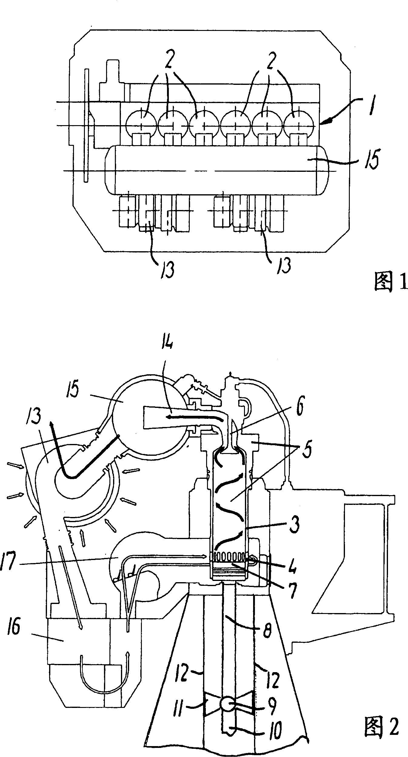
[0030] In the exemplary embodiment of FIG. 1 , a two-stroke internal combustion engine 1 has six cylinders 2 arranged in a single row (tandem engine). The engine may have other numbers of cylinders, for example 4 to 15 cylinders. The engine can be made, for example, from MAN B&W diesels and MC or ME type diesels, or from W_rtsil_ of the Sulzer RT-flex or Sulzer RTA type, or from Mitsubishi. These cylinders may have a bore diameter in the range of eg 25-120 cm, preferably 35-120 cm, more preferably 50-110 cm. The engine has a power range of, for example, 270-8500 kW per cylinder, preferably 1000-7000 kW. Therefore, the engine of the present invention is a large engine.

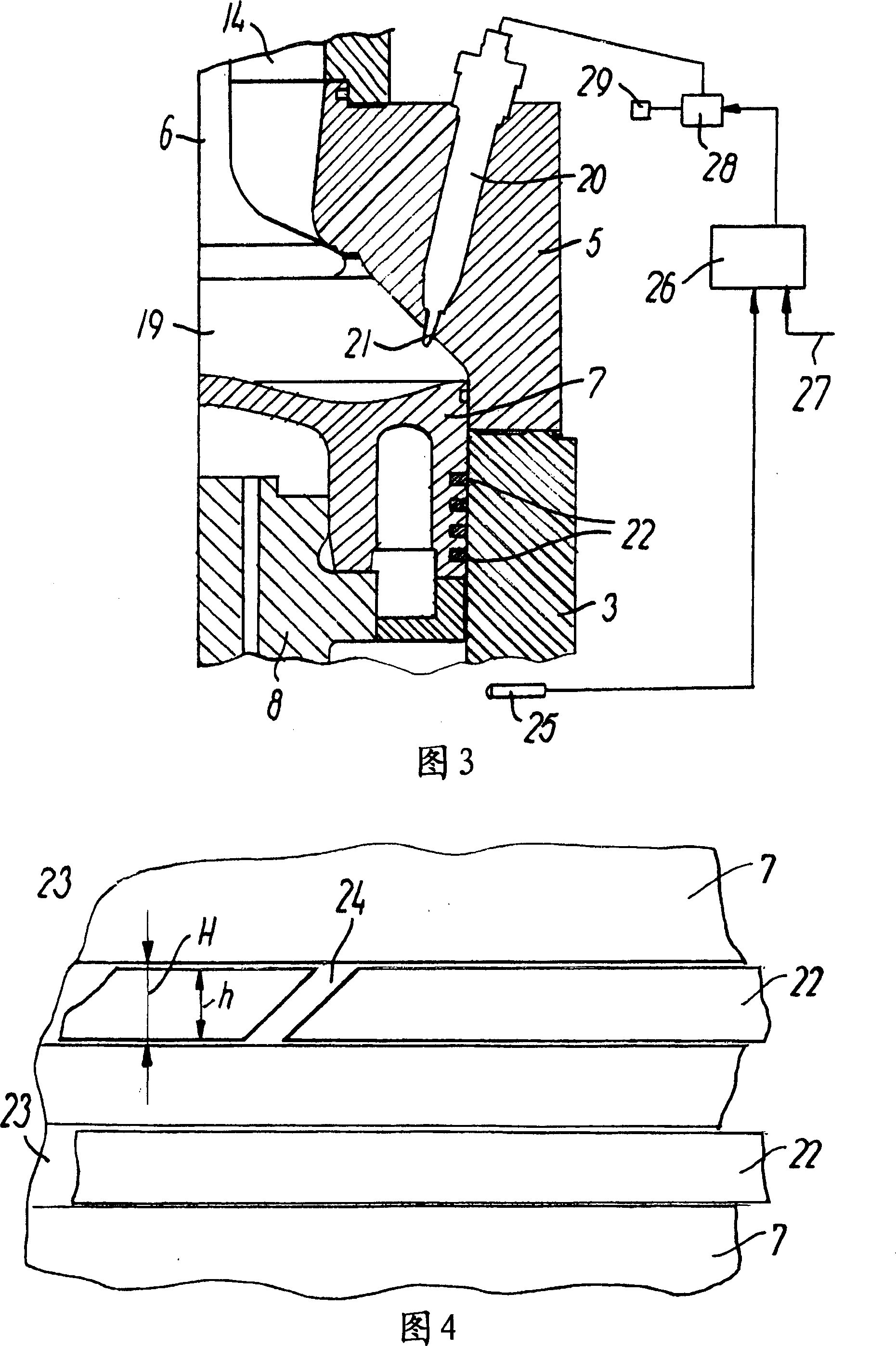
[0031] Each cylinder 2 has a cylinder liner 3 with a row of exhaust holes 4 at its lower end, a cylinder head 5 and an exhaust valve 6 positioned at the upper end of the cylinder liner. The piston 7 is mounted on a piston rod 8 . The piston rod is conventionally connected to a crankpin on a crankshaft (not ...


PUM


Abstract

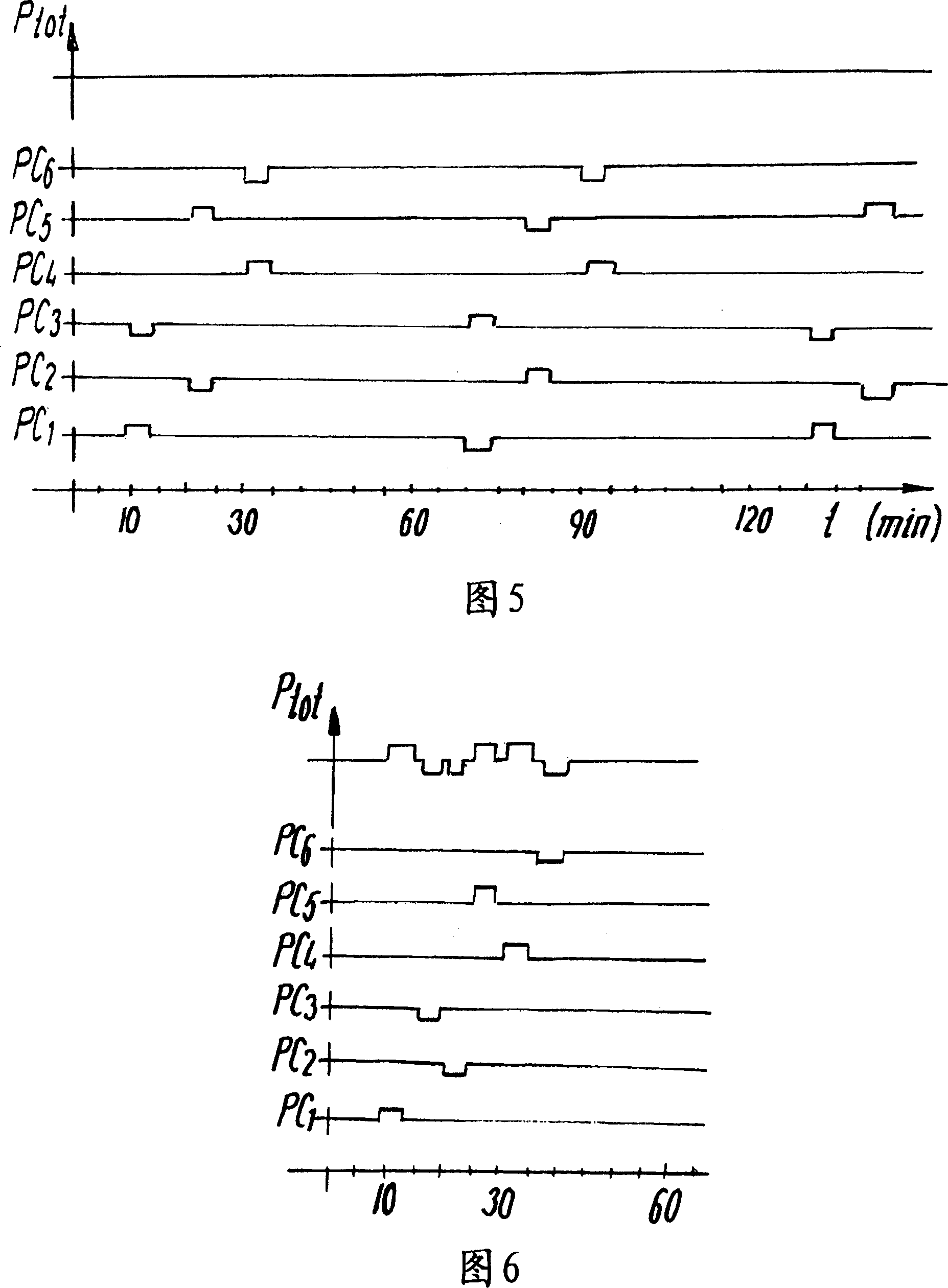
In a crosshead type two-stroke internal combustion engine, the rotation position of piston ring relative to adjacent piston is forcibly changed in the below way. Because the engine is set to continuously run at preset constant load or constant speed, the forcible change of the rotation position of piston in cylinder is effected by at least load fluctuation on the cylinder, so that the mean effective pressure in the cylinder changes at least 0.5bar, and is effected by keeping the changed load for a certain time in the said cylinder.

Description

technical field [0001] The invention relates to a method for forcing a change in the rotational position of a piston ring relative to an adjoining piston in a crosshead two-stroke internal combustion engine, and to such a two-stroke internal combustion engine. Background technique [0002] British Patent No. 1 503 255 describes a crosshead two-stroke internal combustion engine with a plurality of cylinders, wherein the cylinders have pistons with piston rings, and for detecting the rotational position of the piston rings relative to the Sensors attached to piston changes. The piston ring is of a specific type provided with a groove on the outer ring surface facing the running surface on the cylinder liner. The groove runs helically between the upper side and the lower side of the piston ring. The sensor is an electronic proximity sensor (inductive sensor) installed in the cylinder liner. Due to the helical run of the grooves it is possible to detect the current approximat...

Claims


Application Information

Patent Timeline
Patent Type & Authority Applications(China)
IPC IPC(8): F02F5/00
CPCF16J9/22F16J9/24F16J10/02Y10S277/908Y10S277/909
Inventor 耶斯佩尔·W·福格
Owner MAN DIESEL & TURBO FILIAL AF MAN DIESEL & TURBO SE TYSKLAND
Why Eureka
Try Eureka