Supercharge Your Innovation With Domain-Expert AI Agents!

A kind of sinusoidal stepped horn-shaped sound transducer and energy conversion method

An acoustic transducer and horn-shaped technology, which is applied in the field of sinusoidal stepped horn-shaped acoustic transducers, can solve the problems of low voltage emission response, large size, and large disc diameter, so as to avoid sound field destructive interference and voltage emission response. The effect of increasing and reducing the size

Active Publication Date: 2021-05-11
SHAANXI NORMAL UNIV
View PDF10 Cites 0 Cited by
  • Summary
  • Abstract
  • Description
  • Claims
  • Application Information

AI Technical Summary

Problems solved by technology

In order to be able to radiate high-power sound waves into the air medium, the mechanical impedance of the transducer must be well matched with the acoustic impedance of the air medium. Currently, the most widely used is a composite bending vibration transducer proposed by Spanish scholar Gallego. It consists of a thin disk-shaped radiator and a piezoelectric sandwich longitudinal vibration transducer to form a composite vibration mode. The transducer is connected to the center of the disk. In the air medium, strong power sound waves are radiated, and the large-area thin disc works in bending vibration mode, but it must ensure that the frequency of the thin disc-shaped radiator and the piezoelectric sandwich longitudinal vibration transducer are consistent to generate resonance when it is used. The design accuracy of the equipment is high. In addition, another disadvantage of this composite bending vibration transducer is that the diameter of the disc is larger, and the lower the frequency, the larger its size, so its volume is larger in the application environment that requires low frequency , Poor directivity in radiation sound field, low voltage emission response

Method used


Image

  • A kind of sinusoidal stepped horn-shaped sound transducer and energy conversion method
  • A kind of sinusoidal stepped horn-shaped sound transducer and energy conversion method
  • A kind of sinusoidal stepped horn-shaped sound transducer and energy conversion method

Examples


Embodiment Construction

[0023] The technical solutions of the present invention will now be further described in conjunction with the drawings and embodiments, but the present invention is not limited to the following implementation situations.

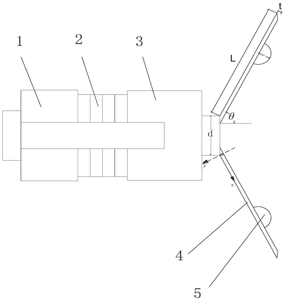
[0024] see figure 1 , the sinusoidal stepped horn-shaped acoustic transducer of the present invention comprises the rear cover plate 1, piezoelectric ceramic stack 2, front cover plate 3 and horn 4 that are arranged on the same axis in sequence, the rear cover plate 1, front cover plate 3 and horn 4 The material is 45# steel, the rear cover 1, the piezoelectric ceramic stack 2 and the front cover 3 are fixed by bolts passing through the central axis, the bottom end of the horn 4 is fixed on the front end of the front cover 3, and the length of the horn 4 is L 30~100mm, the opening angle θ is 30°~75°, the wall thickness t is 1.8~5.4mm, and the working frequency is 15~30kHz. An inwardly protruding circular sinusoidal step 5 is also provided on the inner side ...


PUM


Abstract

The invention belongs to the technical field of mechanical vibration, and relates to a sinusoidal stepped horn-shaped sound transducer and an energy conversion method, including a horn connected to the front cover of the transducer and a sinusoidal ladder vertically arranged inside the horn, and the sinusoidal ladder is arranged inside the horn Between adjacent vibration nodal lines, on the horn section, the intersection point of the front cover plate and the horn busbar is the origin, the extension line of the horn busbar is the x-axis, and the straight line extending from the origin to the protruding direction of the sinusoidal ladder is the y-axis, using the sinusoidal ladder Change the vibration phase of the speaker, the phase at any point on the sine step is πsin (πs), and radiate through the inner surface of the speaker and the sine step surface, and the sound pressure is superimposed on the central axis of the speaker, so that the directivity of the radiation sound field Sharp, voltage-emission response improves. The invention has the characteristics of small size, simple structure, sharp directivity of radiation sound field and high voltage emission response.

Description

technical field [0001] The invention belongs to the technical field of mechanical vibration, and in particular relates to a sinusoidal stepped horn-shaped sound transducer and an energy conversion method. Background technique [0002] The high-power radiated sound waves radiated into the fluid medium (especially into the air medium) have many applications, such as acoustic levitation, acoustic condensation, acoustic dust removal, acoustic repelling of birds, etc. In order to be able to radiate high-power sound waves into the air medium, the mechanical impedance of the transducer must be well matched with the acoustic impedance of the air medium. Currently, the most widely used is a composite bending vibration transducer proposed by Spanish scholar Gallego. It consists of a thin disk-shaped radiator and a piezoelectric sandwich longitudinal vibration transducer to form a composite vibration mode. The transducer is connected to the center of the disk. In the air medium, stron...

Claims


Application Information

Patent Timeline
Patent Type & Authority Patents(China)
IPC IPC(8): H04R17/00
CPCH04R17/005
Inventor 贺西平汪彦军刘强
Owner SHAANXI NORMAL UNIV
Features
  • R&D
  • Intellectual Property
  • Life Sciences
  • Materials
  • Tech Scout
  • Unparalleled Data Quality
  • Higher Quality Content
  • 60% Fewer Hallucinations
Learn More