PBMC separation device and method

A separation device and separation liquid technology, applied in the field of biomedicine, can solve problems such as differences in separation quality, and achieve the effects of high separation efficiency, high separation accuracy, and high analysis accuracy

Pending Publication Date: 2020-01-10
NINGBO JIANYI ELECTRONICS INFORMATION TECH CO LTD
View PDF3 Cites 2 Cited by
  • Summary
  • Abstract
  • Description
  • Claims
  • Application Information

AI Technical Summary

Problems solved by technology

During the separation process, there are often differences in the separation quality of each batch due to the experience, proficiency, and working status of the technicians.

Method used


Image

  • PBMC separation device and method

Examples


specific Embodiment 1

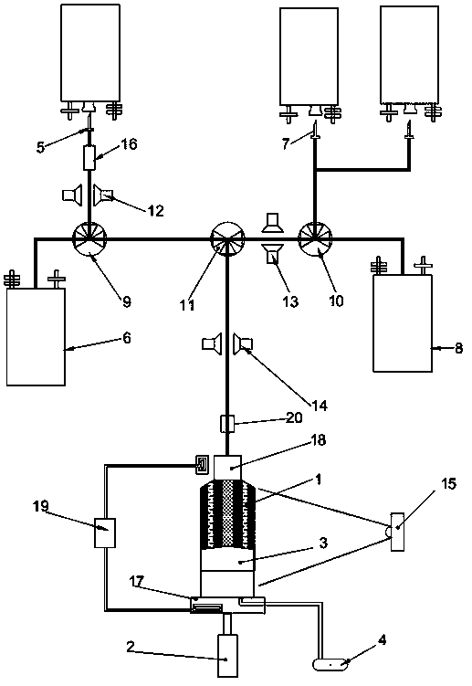
[0034] Specific embodiment one: a kind of PBMC separating device, it comprises controller, centrifugal barrel 1, the first power mechanism that is used to drive centrifugal barrel 1 to rotate, is arranged on the piston 3 in centrifugal barrel 1, is used to drive piston 3 in centrifugal The second power mechanism moving vertically in the barrel 1, the blood sample collection head 5, the separation liquid waste liquid container 6, the cleaning liquid collection head 7, the product collection container 8, the first three-way valve 9, the second three-way valve 10, the first three-way valve Three-way valve 11, the first photoelectric through-beam sensor 12, the second photoelectric over-beam sensor 13, the third photoelectric through-beam sensor 14, the ultrasonic flow sensor 20 and the camera 15 for detecting the position of the piston 3 in the centrifuge barrel 1, so The blood sample collection head 5 and the separation liquid waste liquid container 6 are all connected with the f...

specific Embodiment 2

[0046] The difference between the second embodiment and the first embodiment is that the second embodiment also includes a cooling mechanism 19, mainly to set cooling blocks on the rotating head 18 and the rotating platform 17 to cool the corresponding areas.

specific Embodiment 3

[0047] The third embodiment differs from the first embodiment in that an observation drip 16 is set between the blood sample collection head 5 and the first three-way valve 9 in the third embodiment, which is convenient for the user to observe the blood sample collection and observe the drip 16. There is also a filter mechanism for filtering blood clots.

[0048] The control method of above-mentioned device, it comprises the following steps:

[0049] S1. Connect the blood collection bag with 100ml of blood sample and the cleaning solution bag with 500ml of cleaning solution to the blood sample collection head and the cleaning solution collection head respectively, and inject 100ml of separation liquid into the separation liquid waste container; the separation liquid It is ficoll (the brand is GE, the product number is 17-1440-03), and the cleaning solution is normal saline;

[0050] S2, the centrifuge bucket rotates with a centrifugal force of 800xg, and simultaneously inject...


PUM


Abstract

The present invention relates to the technical field of biomedicine and particularly relates to a PBMC separation device and method. A blood sample collecting head (5) and a separating liquid waste liquid container (6) in the device both communicate with a first three-way valve (9), a washing liquid collecting head (7) and a product collecting container (8) both communicate with a second three-wayvalve (10), besides, the first three-way valve (9), the second three-way valve (10) and a centrifugal barrel (1) all communicate with a third three-way valve (11), a third opposite type photoelectricsensor (14) is arranged between the third three-way valve (11) and an ultrasonic flow sensor (20), the ultrasonic flow sensor (20) is arranged between the third opposite type photoelectric sensor (14) and the centrifugal barrel (1), and besides, a first power mechanism, a second power mechanism, the first three-way valve (9), the second three-way valve (10), the third three-way valve (11), a first opposite type photoelectric sensor (12), a second opposite type photoelectric sensor (13), the third opposite type photoelectric sensor (14) and a camera (15) are all in signal connection with a controller. The separation device has relatively high separation efficiency and also relatively high reliability.

Description

technical field [0001] The invention relates to the technical field of biomedicine, in particular to a PBMC separation device and method. Background technique [0002] With the rise of tumor immunotherapy, chimeric antigen receptor gene-modified T cells (CAR-T) technology has developed rapidly and has become one of the new means of tumor immunotherapy. CAR-T technology is to introduce artificially constructed specific chimeric antigen receptors into T lymphocytes through genetic engineering methods, so that they can specifically recognize and kill the expression-related antigens without the restriction of the major histocompatibility complex. Antigens of tumor cells. [0003] At the beginning of the culture of CAR-T, NK, CIK and other immune cells, PBMCs need to be isolated from peripheral blood. The traditional PBMC separation technology is generally completed manually by cell culture technicians, which is not only cumbersome, but also time-consuming and labor-intensive. ...

Claims


Application Information

Patent Timeline
Patent Type & Authority Applications(China)
IPC IPC(8): C12M1/00C12M1/36C12M1/34C12M1/12C12N5/078
CPCC12M29/04C12M41/00C12M41/44C12N5/0634C12N2509/10
Inventor 何加铭陶雷
Owner NINGBO JIANYI ELECTRONICS INFORMATION TECH CO LTD
Why Eureka
Try Eureka