Novel feeding device for decomposing furnace for cement kiln

A technology of feeding device and decomposition furnace, which is applied in furnaces, furnace components, lighting and heating equipment, etc., can solve the problems of increasing energy consumption, and it is difficult for materials to disperse powder, etc., and achieve the effect that is beneficial to calcination quality and energy saving effect.

Pending Publication Date: 2020-01-10
阿克苏天山多浪水泥有限责任公司
View PDF0 Cites 0 Cited by
  • Summary
  • Abstract
  • Description
  • Claims
  • Application Information

AI Technical Summary

Problems solved by technology

[0002] All new dry-process clinker production lines in my country adopt traditional circular pipes with a large oblique angle to feed the calciner into the calciner. This design is difficult to achieve the effect of dispersing the powder on the material, resulting in two kind of disadvantage
One is that when the insufficiently dispersed material powder enters the calciner and the updraft does not increase, part of the material powder will directly fall into the bottom and enter the kiln. This kind of material will have a certain impact on the quality of clinker. In this case, we usually adopt a solution to increase the amount of coal head to increase the calcination temperature. In addition, increase the power of the high-temperature fan to increase the air volume and enhance the upward force of the updraft to bring the material into the five-stage preheater. Increase the power of the high-temperature fan , will virtually increase energy consumption

Method used


Image

  • Novel feeding device for decomposing furnace for cement kiln
  • Novel feeding device for decomposing furnace for cement kiln
  • Novel feeding device for decomposing furnace for cement kiln

Examples


Embodiment Construction

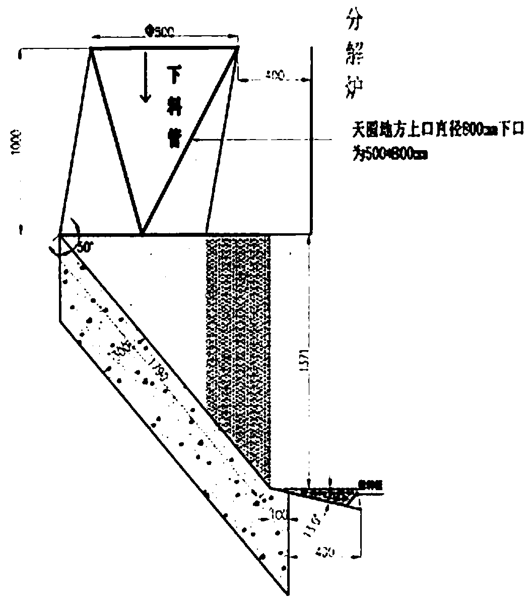
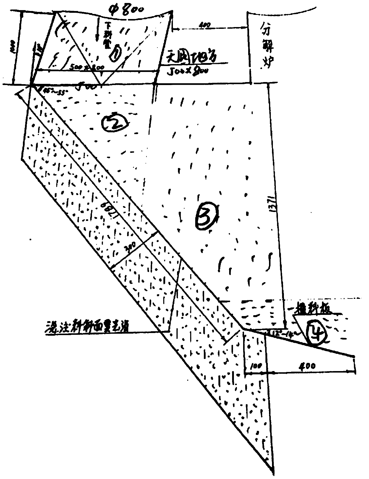
[0016] Such as Figure 1-3 As shown, the invention discloses a novel feeding device for a cement kiln calciner.

[0017] The area Ⅰ1 on the upper part of the feed end adopts a rectangular feed inlet. When the material enters this area, the material changes from cylindrical to rectangular with a flat material curtain and enters the area Ⅱ2 of the device. The feeding section of the device area Ⅰ1 adopts an outward slope method. It is to ensure that all materials enter the area II2 of the device.

[0018] The area II2 of the device is to disperse the viscous material from the upper stage and properly reduce the flow rate of the material. The area II2 is located directly below the bottom feed port of the area I1.

[0019] When the area III3 of the device introduces the material into the area IV4 of the device at an appropriate angle and flow rate, the material is dispersed for the second time; the area III3 is located below the area II2, and is located on the same slope as the ar...


PUM

PropertyMeasurementUnit
Diameteraaaaaaaaaa
Vertical heightaaaaaaaaaa

Abstract

The invention discloses a novel feeding device for a decomposing furnace for a cement kiln. The novel feeding device comprises an area I, an area II, an area III and an area IV, wherein the area I comprises a blanking pipe with the round top and the square bottom, and the blanking pipe is arranged obliquely; the area II is positioned below the feeding port of the area I, the area III is positionedunder the area II, and the area III and the area II are positioned on the oblique plane with the same gradient; and the area IV is connected to the bottom end of the area III and comprises a materialscattering plate which is tilted downwards. The novel feeding device for the decomposing furnace enhances the dispersion of materials to ensure the effective mixing of the materials with the rising high-temperature airflow in the decomposing furnace, so that all the materials are taken to a 5-stage preheater and deposited into the kiln. Thus, raw materials can be fully and uniformly decomposed, which is conducive to the calcination quality and an energy saving effect.

Description

technical field [0001] The invention belongs to the technical field of cement kiln production, in particular to a novel feeding device for a cement kiln calciner. Background technique [0002] All new dry-process clinker production lines in my country adopt traditional circular pipes with a large oblique angle to feed the calciner into the calciner. This design is difficult to achieve the effect of dispersing the powder on the material, resulting in two kind of disadvantage. One is that when the insufficiently dispersed material powder enters the calciner and the updraft does not increase, part of the material powder will directly fall into the bottom and enter the kiln. This kind of material will have a certain impact on the quality of clinker. In this case, we usually adopt a solution to increase the amount of coal head to increase the calcination temperature. In addition, increase the power of the high-temperature fan to increase the air volume and enhance the upward forc...

Claims


Application Information

Patent Timeline
IPC IPC(8): F27D3/00
CPCF27D3/0084F27D2003/0093
Inventor 李志旺王振芳李正军陈杰米新江肖建襄姚继忠马英朱晓明
Owner 阿克苏天山多浪水泥有限责任公司
Why Eureka
Try Eureka