Discarding petal capable of reducing fluid resistance

A technology of fluid resistance and flaps, applied in the direction of offensive equipment, rocket launchers, weapon types, etc., can solve the problems of sudden drop in launch speed, bending deformation, and not easy to bend and deform, so as to increase the launch speed and reduce bending deformation , the effect of reducing resistance

Active Publication Date: 2020-01-10
NANJING UNIV OF SCI & TECH
View PDF6 Cites 3 Cited by
  • Summary
  • Abstract
  • Description
  • Claims
  • Application Information

AI Technical Summary

Problems solved by technology

[0003] The front end of the existing card flap is usually an annular disc, which is not easy to bend and deform when it is out of the chamber
However, it has been found in practice that the following problems exist when using a clip with an annular disc at the front end for underwater launch: First, when the clip exits the chamber, the supercavitation formed by the projectile is not enough to wrap the clip , so that the entire annular disk of the clamping valve will be subject to greater pressure, resulting in huge resistance, which can cause a sudden drop in the firing speed in a very short time after being discharged from the chamber; second, during this period, the clamping valve and the bullet The resistance of the body is very different, and the resistance of the clamping flap is much greater than that of the projectile. Due to the inertial effect, the annular boss that matches the two will be subject to a large shear force, and bending deformation will occur, which will cause interference when the clamping flap is detached.

Method used


Image

  • Discarding petal capable of reducing fluid resistance
  • Discarding petal capable of reducing fluid resistance
  • Discarding petal capable of reducing fluid resistance

Examples


Embodiment Construction

[0022] In order to illustrate the present invention more clearly, the present invention will be further described in detail below in conjunction with the accompanying drawings and embodiments.

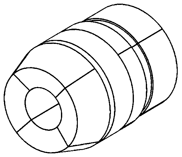
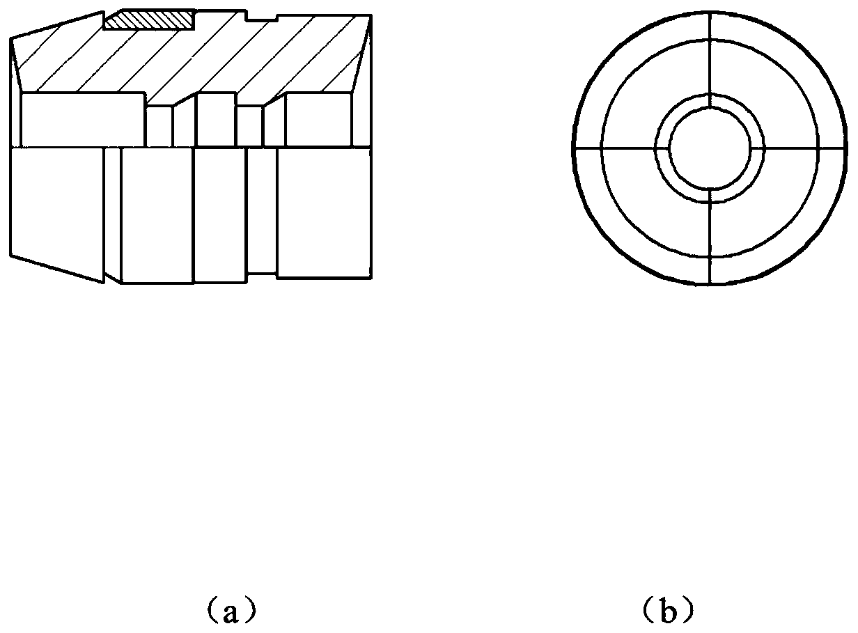
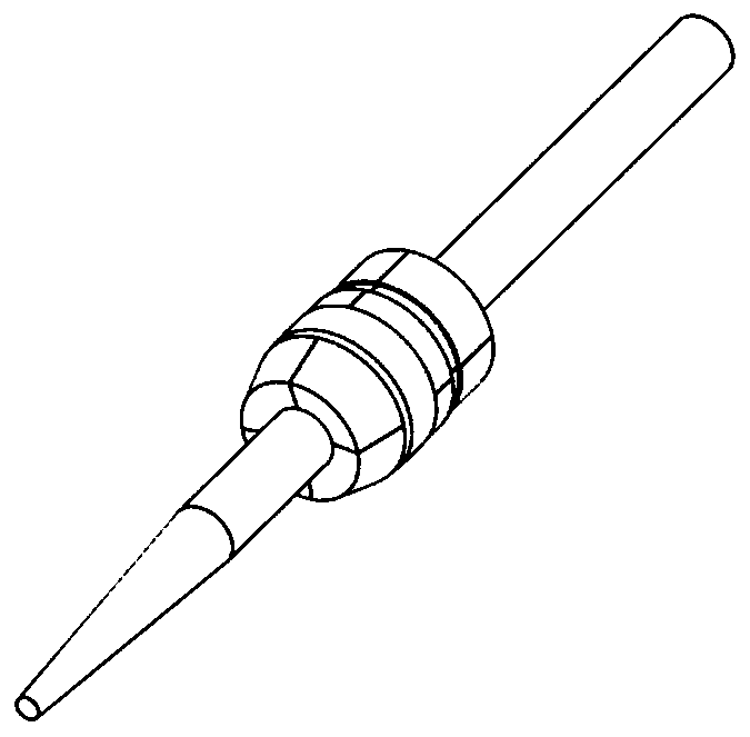
[0023] refer to figure 1 , image 3 , The shelling flap of the present invention which reduces fluid resistance is composed of 4 flaps, which cooperate with projectiles through the multi-section bosses in the internal through holes, and are fixed by matching with elastic belts.

[0024] refer to figure 1 , figure 2 and image 3 , The shelling valve with reduced fluid resistance of the present invention has a frustum-shaped front end, and compared with ordinary cylindrical valves, the force-bearing surface of the front end is reduced by more than 40%. The front end faces inward with a certain inclination angle, and there is an outward radial force under the action of water flow, and the front end of the card flap is easy to separate outward after being discharged from the bore.

...


PUM


Abstract

The invention belongs to the field of underwater launching, and in particular relates to a discarding petal capable of reducing fluid resistance. The discarding petal is formed by fastening four petals through an annular elastic belt, and is divided into a front-end circular-truncated-cone segment and a rear-end cylindrical segment, wherein the front end surface of the circular truncated cone hasan inclination angle inward. The interior of the discarding petal is provided with a through hole, and the rear end surface of the discarding petal has an inclination angle inward. The diameter D1 ofthe front end of the circular truncated cone of the discarding petal is determined by the cavitation diameter D formed by the projectile on the front end surface of the discarding petal, and D1 is 2-3mm larger than D2. According to the discarding petal provided by the invention, when the discarding petal leaves the chamber, water flows impact on thecircular-truncated-cone-shaped front end surface, and the front end surface becomes a cavitation device of the discarding petal, so that cavitation capable of wrapping the discarding petal is formed, the stress area of the front end surface of thediscarding petal is reduced by 40% or above, the resistance to the discarding petal leaving the chamber can be reduced to a certain extent, and the underwater launching speed is improved. The front end of the discarding petal adopts a circular truncated cone structure so as to reduce the bending deformation of the front end of the discarding petal.

Description

technical field [0001] The invention belongs to the field of underwater launching, and in particular relates to a shelling valve for reducing fluid resistance. Background technique [0002] With the development and application of new technologies, modern naval warfare has put forward new requirements for various offensive and defensive weapons and equipment of the navy. It has good performance and has become the focus of the development of naval weapons and equipment in various countries. The supercavitation projectile is a new concept weapon that utilizes the principle of supercavitation drag reduction. It breaks through the movement limit of traditional projectiles in water, and greatly enhances the underwater range and damage capability. In order to increase the initial velocity of the supercavitating projectile under water, the shelling flap is usually used to increase the action area of ​​the gunpowder force. [0003] The front end surface of the existing flap is usua...

Claims


Application Information

Patent Timeline
Patent Type & Authority Applications(China)
IPC IPC(8): F41F3/07
CPCF41F3/07
Inventor 郭则庆陈伟善刘如石
Owner NANJING UNIV OF SCI & TECH
Why Eureka
Try Eureka