

Soil detection device
A technology of soil detection and surface installation, applied in the direction of sampling devices, etc., can solve problems such as low work efficiency, soil corrosion, skin damage, etc., and achieve the effect of improving work efficiency, reducing work intensity and improving work efficiency
- Summary
- Abstract
- Description
- Claims
- Application Information
AI Technical Summary
Problems solved by technology
Method used
Image

Examples
Embodiment 1
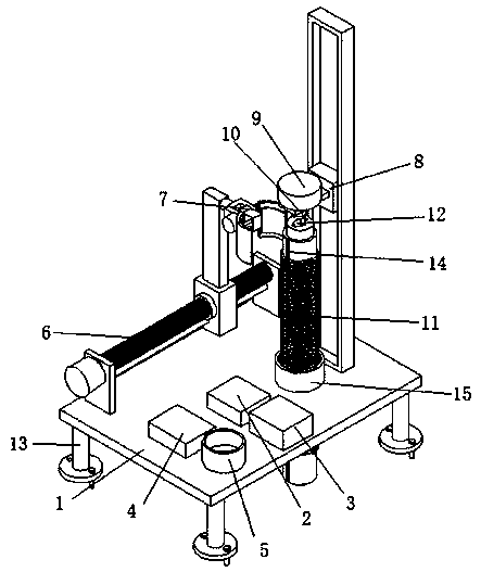
[0031]A soil detection device, comprising a console 1, a longitudinal adjustment mechanism 8 and a sampling mechanism 11; a fixing mechanism 13 is installed on the lower surface of the console 1, and a horizontal adjustment mechanism 6 is installed on the left part of the upper surface of the console 1, and the horizontal adjustment mechanism 6 is equipped with a clamping mechanism 7, the upper surface rear of the console 1 is equipped with a longitudinal adjustment mechanism 8 and a fixed pipe 15, the inner surface of the fixed pipe 15 is provided with an internal thread, and the internal thread of the fixed pipe 15 is equipped with a sampling mechanism 11, The right part of the upper surface of the console 1 is sequentially installed with a soil moisture meter 2, a soil tester 3, a single-chip microcomputer 4 and a drying box 5; A fixed plate 803 is installed on the motor 802, a third servo motor 9 is installed on the upper surface of the fixed plate 803, and a plunger 10 is ...
Embodiment 2
[0033] This embodiment differs from Embodiment 1 in that:
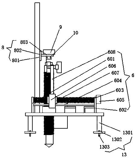
[0034] In this embodiment, the lateral adjustment mechanism 6 includes a bearing seat 601 and a fixed seat 602, a first servo motor 605 is installed on the outer surface of the fixed seat 602, a lead screw 603 is rotatably installed on the bearing seat 601, and the end of the lead screw 603 is connected to the The fixed seat 602 is connected, the output shaft end of the first servo motor 605 is connected with the lead screw 603, a slide bar 604 is installed between the bearing seat 601 and the fixed seat 602, and a slide block 606 is slidably installed on the slide bar 604, and the slide block 606 Leading screw nut 607 is installed on it, and leading screw nut 607 is connected with leading screw 603, and the upper surface of sliding block 606 is equipped with support 608, and first servo motor 605 is electrically connected with single-chip microcomputer 4, is convenient to adjust clamping mechanism 7 and is lateral pos...
Embodiment 3
[0037] This embodiment differs from Embodiment 1 in that:
PUM
 Abstract
Description
Claims
Application Information