Pipe opening device and hole opening method

A technology for pipes and pipe fittings, which is applied in the field of pipe opening devices and openings, can solve the problems of time-consuming, laborious, poor adjustability, and large deviation in changing punches, and achieves fast and accurate positioning adjustment, convenient replacement, and good positioning accuracy. Effect

Pending Publication Date: 2020-01-14
四川龙立可不锈钢管业有限公司
View PDF0 Cites 1 Cited by
  • Summary
  • Abstract
  • Description
  • Claims
  • Application Information

AI Technical Summary

Problems solved by technology

[0004] The object of the present invention is to propose a pipe hole opening device and hole opening method, which solves the problems of inaccurate positioning of pipe fittings, poor adjustability, low positioning stability of pipe fittings, large deviation, and problems when replacing punches. time consuming problem

Method used


Image

  • Pipe opening device and hole opening method
  • Pipe opening device and hole opening method
  • Pipe opening device and hole opening method

Examples


Embodiment 1

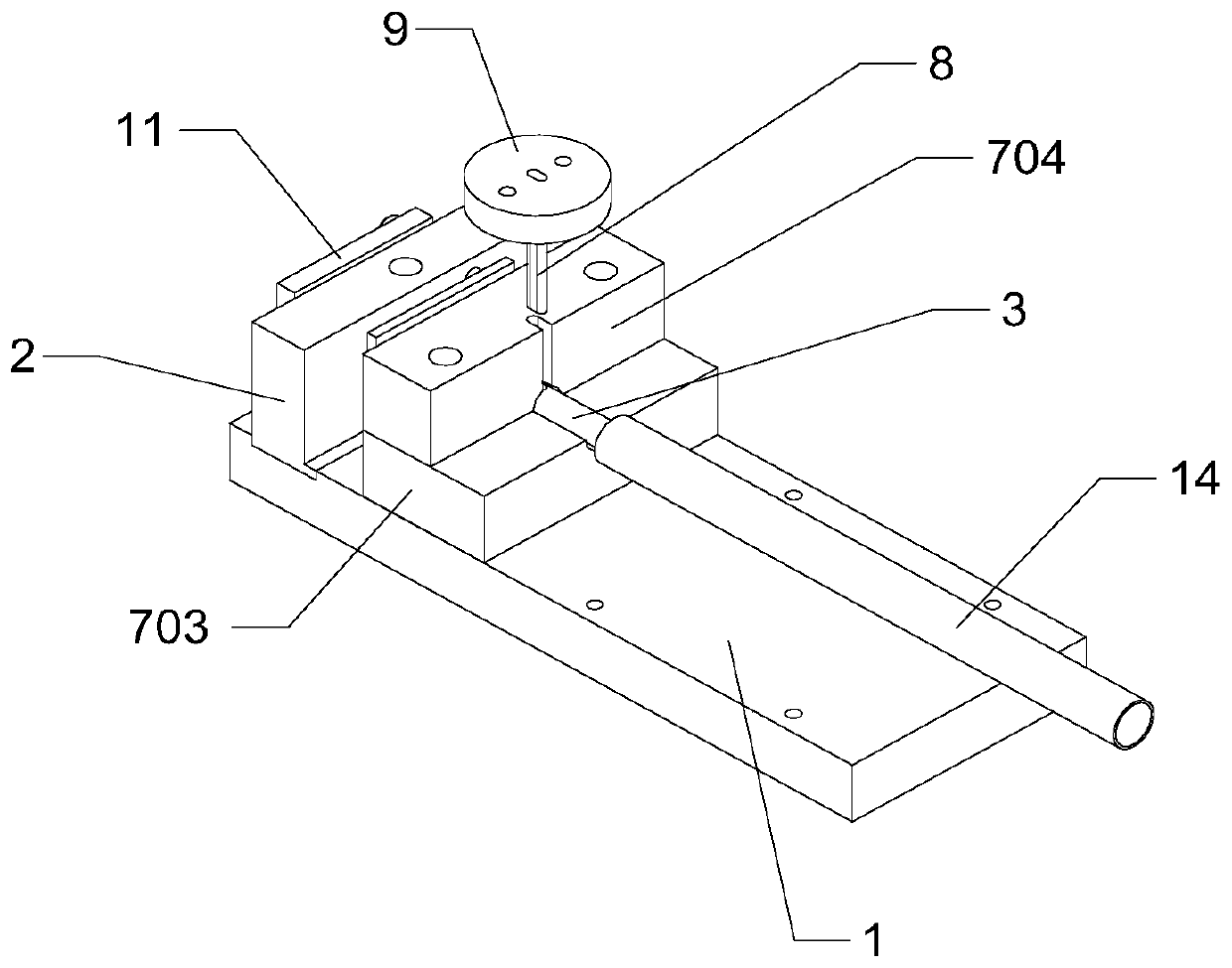
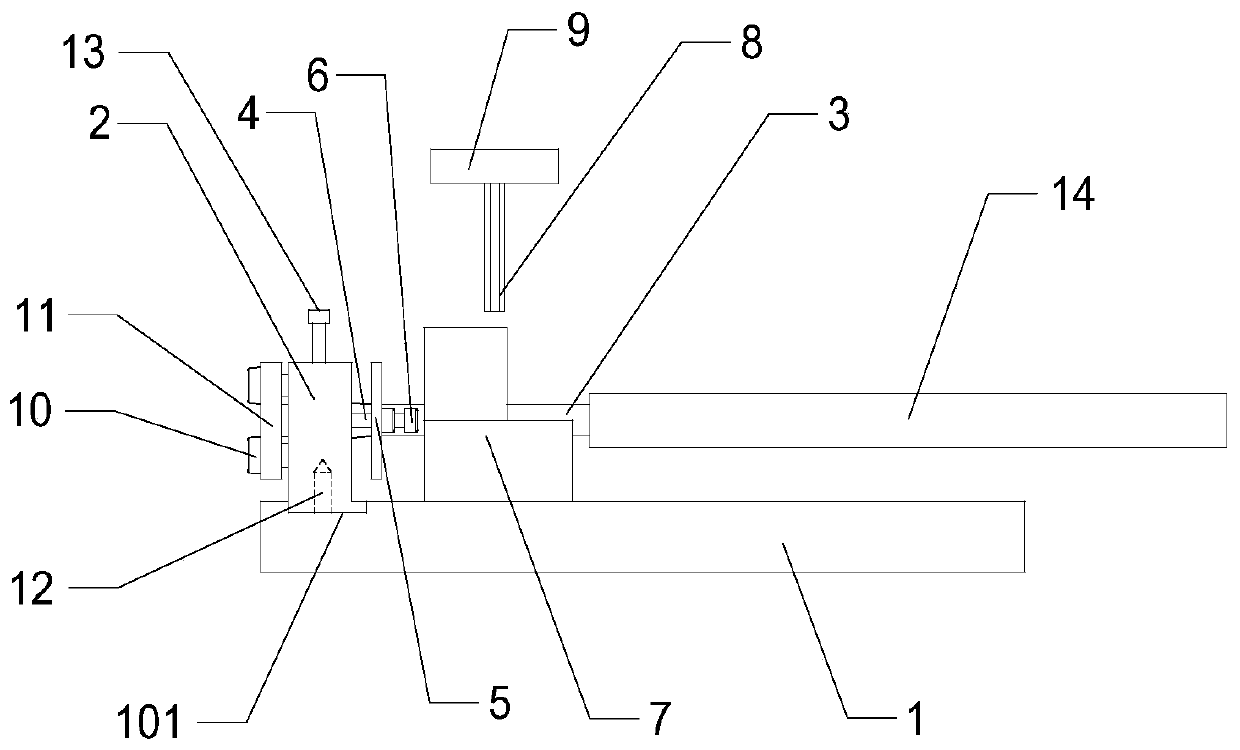
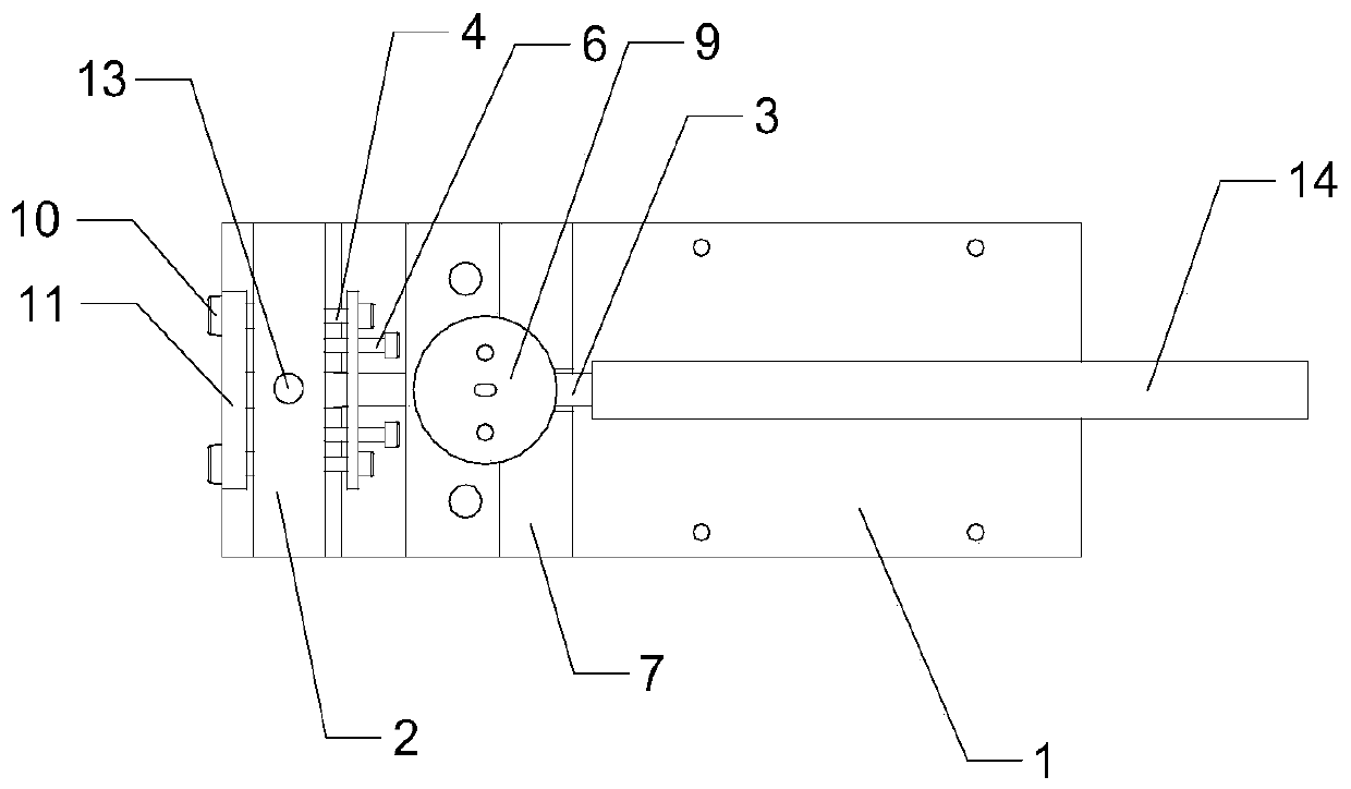
[0040] Such as Figure 1-5 As shown, the present invention is a pipe hole opening device, including a base plate 1, a positioning boss 2 and a punch 3 installed on a machine tool workbench, the base plate 1 is provided with a groove 101, and the positioning boss 2 The bottom of the bottom is adapted to the groove 101 and installed on the base plate 1, and the middle part of the positioning boss 2 is provided with a first through hole 201; the front side of the positioning boss 2 is fixed with a positioning adjustment plate 5 by a bolt A4, so The positioning adjustment plate 5 is provided with a second through hole 501, and the positioning adjustment plate 5 is also threaded with an adjustment bolt 6; it also includes a positioning pad 7 fixed on the bottom plate 1, and the positioning pad 7 is arranged on the positioning adjustment plate. 5, the positioning pad 7 is provided with a third through hole 701, the punch 3 runs through the first through hole 201, the second through ...

Embodiment 2

[0043] This embodiment is a further description of the present invention.

[0044] Such as Figure 1-5 As shown, this embodiment is based on Embodiment 1. In a preferred embodiment of the present invention, the punch 3 includes a first circular platform 303 and a cylinder A302 and a cylinder B304 connected to both ends of the first circular platform 303, and the cylinder The diameter of A302 is greater than the diameter of the cylinder B304, the cylinder A302 and the side of the first round platform 303 are also provided with a cutting surface, the punching hole 301 is set on the cylinder B304, the cylinder A302 is matched with the first through hole 201 and runs through The first through hole 201 of the positioning boss 2 is positioned.

[0045] With the above-mentioned structure, the first round table 303 is set between the cylinder A302 and the cylinder B304, and the original stress points of the punch 3 are distributed to each stress area of ​​the punch 3, so that the fix...

Embodiment 3

[0050] This embodiment is a further description of the present invention.

[0051] Such as Figure 4 As shown, this embodiment is based on the above, in a preferred embodiment of the present invention, the positioning pad 7 includes a lower pad 703 and an upper pad 704, and the third through hole 701 includes openings in the lower pad 703 The arc-shaped through groove A7011 on the top and the arc-shaped through groove B7012 on the pad 704. With the above structure, the upper cushion block 704 and the lower cushion block 703 are fixed together by bolts, and the through slot A7011 is matched with the through slot B7012 to form the third through hole 701 .

[0052] In a preferred embodiment of the present invention, the arc lengths of the through groove A7011 and the through groove B7012 are equal.


PUM


Abstract

The invention discloses a pipe opening device and a hole opening method. The pipe opening device comprises a bottom plate, a positioning boss and a punching rod, wherein the bottom plate, the positioning boss and the punching rod are mounted on a machine tool workbench, a groove is formed in the bottom plate, the bottom of the positioning boss is matched with the groove to be installed on the bottom plate, and a first through hole is formed in the middle of the positioning boss; a positioning adjusting plate is fixed to the front side of the positioning boss through a bolt A, a second throughhole is formed in the positioning adjusting plate, and an adjusting bolt is also in threaded connection with the positioning adjusting plate; and the pipe opening device comprises a positioning pad, the positioning pad is arranged on the front side of the positioning adjusting plate, a third through hole is formed in the positioning pad, the punching rod penetrates through the first through hole,the second through hole and the third through hole, a punching groove is further formed in the positioning pad, and the punching groove is in communication with the third through hole. The pipe opening device has the advantages that the pipe is accurate in positioning and high in stability, and the positioning adjusting plate can be adjusted to be suitable for pipes with different lengths.

Description

technical field [0001] The invention relates to the field of drilling devices, in particular to a pipe drilling device and a drilling method. Background technique [0002] A steel pipe is a steel product with openings at both ends and a hollow section, and the ratio of its length to the perimeter of the section is large. When the ratio of the length to the perimeter of the section is small, it can be called a pipe section or a tubular fitting, which belongs to the category of pipe fittings. Among them, stainless steel pipes are A hollow, elongated round steel material that is widely used in petroleum, chemical, medical, food, light industry, mechanical instrumentation and other industrial pipelines and mechanical structural components. Modern production is inseparable from steel pipes, and steel pipes often need to be drilled during installation or connection. Steel pipe drilling is one of the common processes in steel pipe processing. [0003] The perforating device of the...

Claims


Application Information

Patent Timeline
Patent Type & Authority Applications(China)
IPC IPC(8): B21D28/28B21D43/00
CPCB21D28/28B21D43/003
Inventor 肖波吴俊张棣高仕铭陶航
Owner 四川龙立可不锈钢管业有限公司
Why Eureka
Try Eureka