Punching process of wood tray special-shaped hole
A technology of special-shaped holes and wooden pallets, which is applied in the direction of engine lubrication, fixed drilling machines, engine components, etc., to achieve the effects of low resistance, reduced wear, and reduced wear
- Summary
- Abstract
- Description
- Claims
- Application Information
AI Technical Summary
Problems solved by technology
Method used
Image

Examples
Embodiment 1
[0039] A process for punching special-shaped holes in wooden pallets, comprising the following process steps:
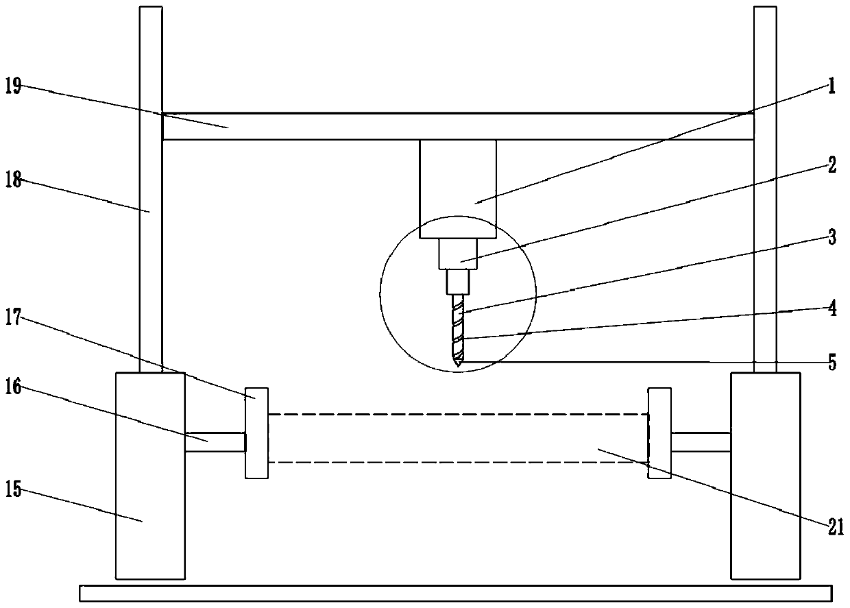
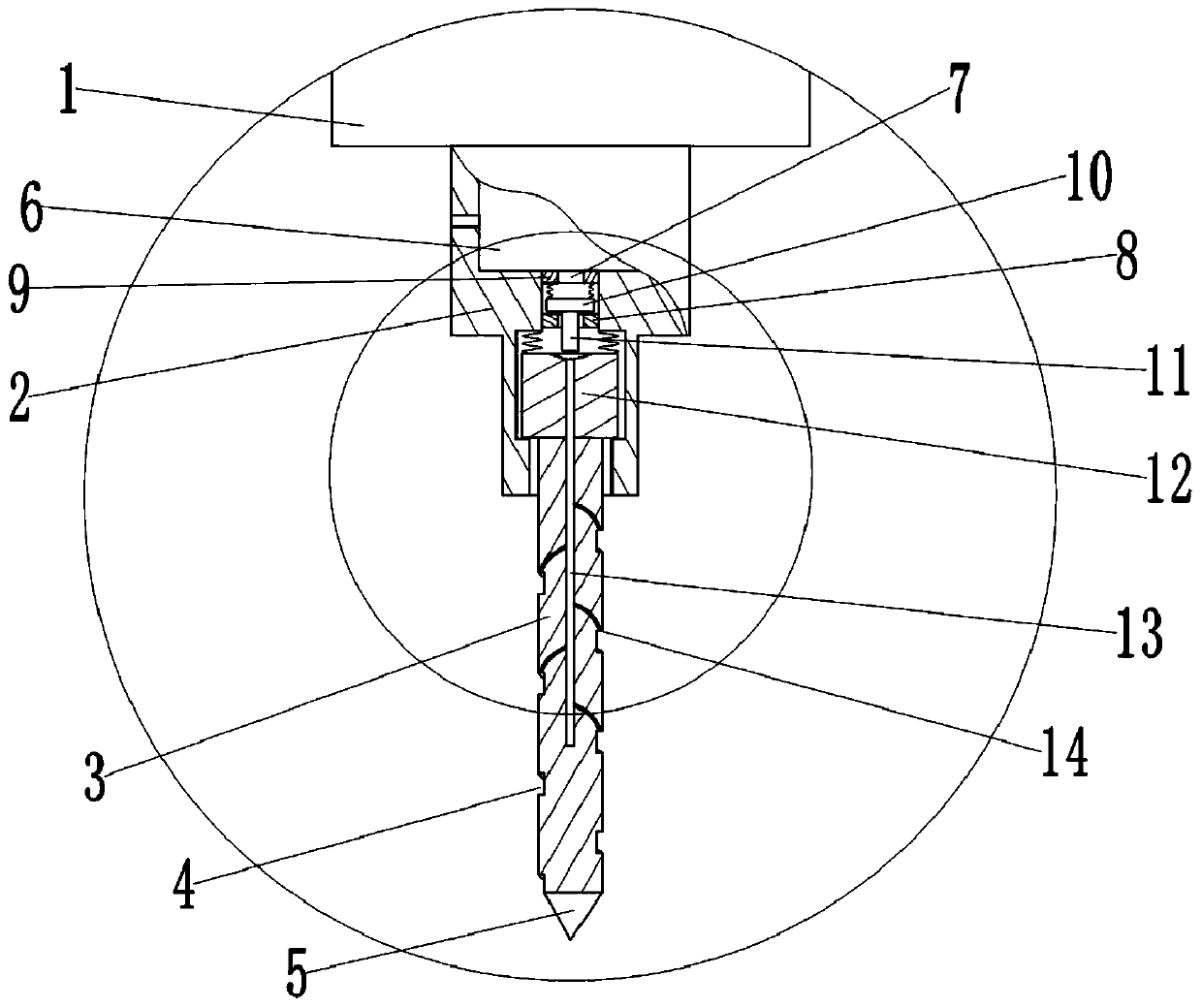
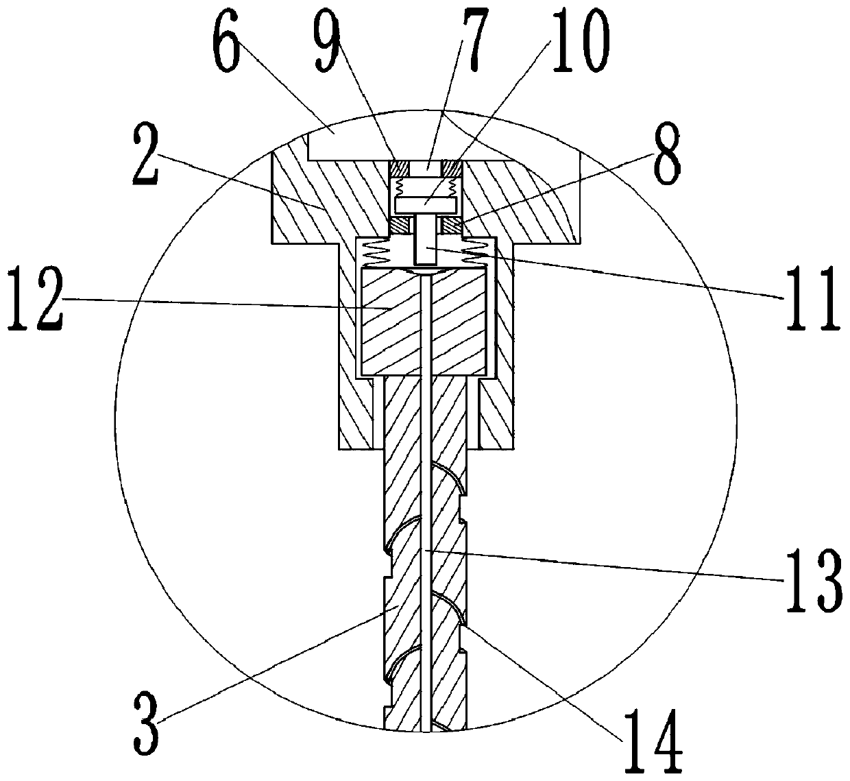
[0040] Step A, scribing and preparing the punching device: according to the construction drawing of the wood 21, determine the position on the wood 21 to be drilled, and draw a marking line on the wood 21 where the hole needs to be drilled. Use the punching device, if attached figure 1 As shown, the punching device includes a punching machine 1, and the lower end of the punching machine 1 is connected with a mounting head 2 through a shaft hole, such as figure 2 , image 3 As shown, a drill bit 3 is vertically slidably connected to the mounting head 2. Specifically, a rectangular column 12 is integrally formed on the drill bit 3. The cross section of the rectangular column 12 is square. Guide groove, the upper end of rectangular post 12 is welded with first elastic reset piece, and the first elastic reset piece selects stage clip for use, and the upper end of the ...
Embodiment 2
[0050] The difference between the present embodiment and the first embodiment is that when the special-shaped hole is processed on the wood 21, after the position to be drilled is determined according to the construction drawing, the starting point for the drill bit 3 to be drilled into the wood 21 is determined according to the position of the hole to be drilled and the shape of the hole. The starting point and the trajectory and feed rate of the drill bit. For example, when drilling an elliptical hole on the wood 21, the long axis end point of the elliptical hole is selected as the starting point. After the drill bit enters the wood, walk along the elliptical track line drawn on the wood to obtain an ellipse on the wood. hole.
Embodiment 3
[0052] Such as Figure 5 As shown, the difference between this embodiment and Embodiment 1 lies in the clamping mechanism. Take the clamping mechanism on the left side of the figure as an example for illustration. The inside of the vertical telescopic rod 18 is hollow, and the right side of the clamping block 17 is glued and fixed. Connected with a clamping airbag 22, the clamping airbag 22 is divided into an upper clamping airbag and a lower clamping airbag, the upper clamping airbag and the lower clamping airbag are respectively located on the upper and lower sides of the fixed block, and the clamping block 17 is provided with The air flow passage, the upper clamping airbag and the lower clamping airbag are all connected with the airflow passage, and the left end of the airflow passage is communicated with a flexible pipe 23, and the left end of the flexible pipe 23 communicates with the inside of the vertical telescopic rod 18, and the clamping airbag 22 also Connected with...
PUM
 Abstract
Description
Claims
Application Information
 - R&D
- Intellectual Property
- Life Sciences
- Materials
- Tech Scout
- Unparalleled Data Quality
- Higher Quality Content
- 60% Fewer Hallucinations
Browse by: Latest US Patents, China's latest patents, Technical Efficacy Thesaurus, Application Domain, Technology Topic, Popular Technical Reports.
© 2025 PatSnap. All rights reserved.Legal|Privacy policy|Modern Slavery Act Transparency Statement|Sitemap|About US| Contact US: help@patsnap.com