
Flat bottom structure sublevel rock drilling stage ore removal subsequent cut-and-filling stoping method

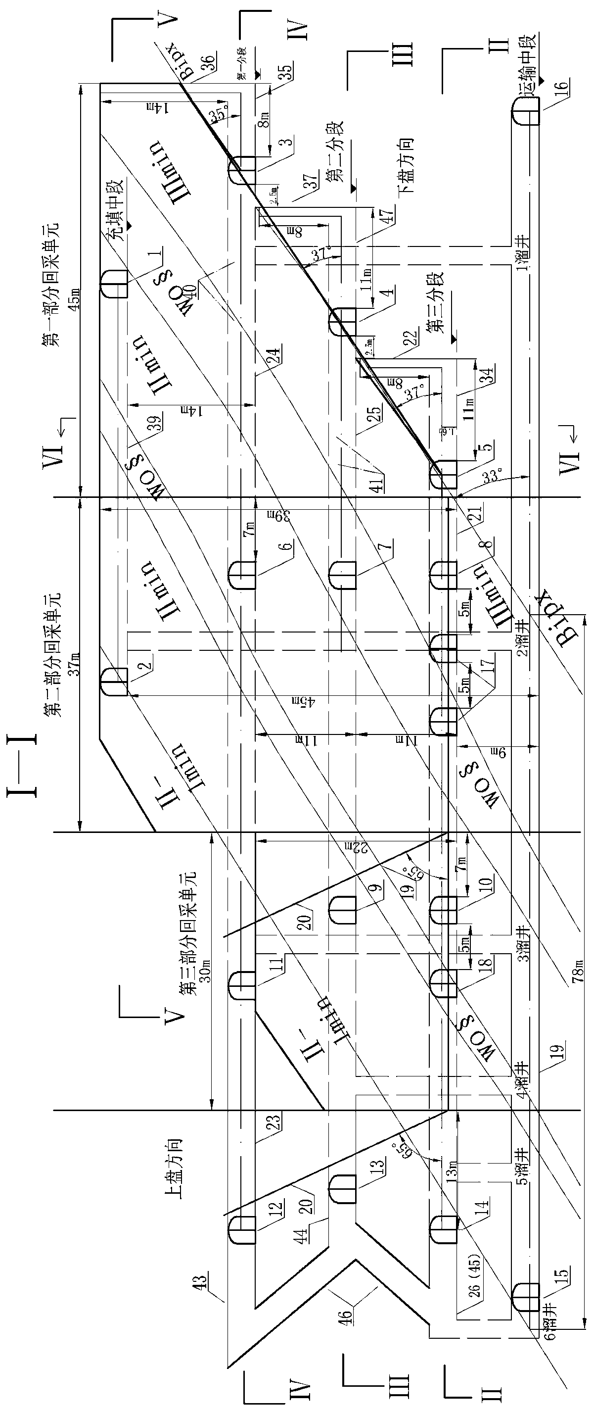
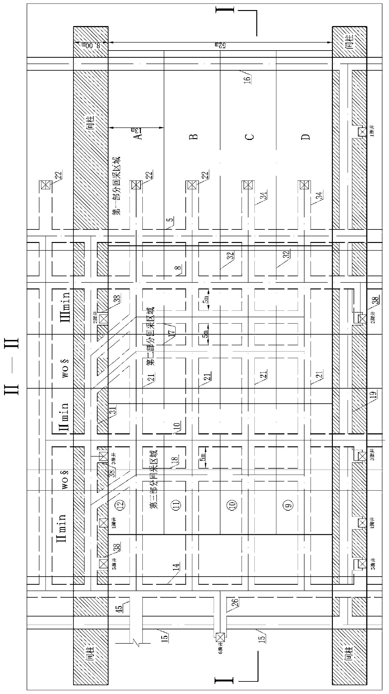
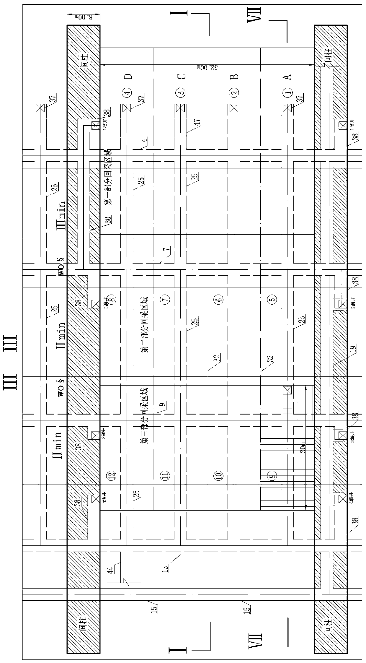
A backfill mining method and segmented technology, which is applied in the fields of backfill, ground mining, mining equipment, etc., can solve the problems of low recovery rate, long mining and filling cycle time, and easy roof extraction in the room-and-pillar backfill mining method.

Active Publication Date: 2020-01-14
HEBEI PROVINCE FANSHAN PHOSPHORITE CO LTD
View PDF6 Cites 3 Cited by
  • Summary
  • Abstract
  • Description
  • Claims
  • Application Information

AI Technical Summary

Problems solved by technology

However, the "segmented rock drilling stage mining method followed by filling mining" is generally applied to ore body stabilization, and the ore body occurs in a steeply inclined ore body, that is, the ore body dip angle is greater than 55°, which is convenient for concentrated ore extraction from the bottom segment , the other auxiliary sections are only responsible for rock drilling, charge blasting, and loose ore; in inclined (ore body dip angle 30°-55°) ore bodies, the application of the "segmented rock drilling stage and subsequent filling mining method" has ore At the same time, there are also problems such as large exposed area of ​​the roof, long mining and filling cycle time, easy leakage of the roof of the mining house, and high safety risks. It is easy to cause the roof to fall, and the mining difficulty of other mines will be increased after the ground pressure appears; the room-and-pillar filling mining method has problems such as low recovery rate
[0003] Therefore, there is a contradiction between efficiency, safety, cost, dilution and loss in the mining of complex environments with moderately stable orebody stability, steeply inclined and extremely thick inclined orebodies.

Method used


Image

  • Flat bottom structure sublevel rock drilling stage ore removal subsequent cut-and-filling stoping method
  • Flat bottom structure sublevel rock drilling stage ore removal subsequent cut-and-filling stoping method
  • Flat bottom structure sublevel rock drilling stage ore removal subsequent cut-and-filling stoping method

Examples


Embodiment

[0085] It is suitable for "three-under" mining bodies such as the overlying high-pressure aquifer of the ore body. The roof of the ore body is stable and the surrounding rock of the floor of the ore body is unstable. The ore body is moderately stable, with rocks between the ore body and the ore body. Soft and hard interbedded, with well-developed joints and fissures, with obvious layer-like structure, resulting in obvious differences in the mechanical strength of the ore body, rock inclusions and surrounding rocks of the roof and floor. It is suitable for ore bodies with a horizontal thickness greater than 40m and a long strike. The steeply inclined ore body with an inclination angle greater than 55°, and the friction force of the contact surface between the bottom wall of the ore body and the surrounding rock of the floor is relatively small, and the ore has good fluidity. The moving angle of the ore bottom wall is above 30° and the inclination angle is 30-55° Mining of metalli...


PUM

PropertyMeasurementUnit
Heightaaaaaaaaaa
Lengthaaaaaaaaaa

Abstract

The invention relates to the technical field of mining of metal and non-metal ores, in particular to a flat bottom structure sublevel rock drilling stage ore removal subsequent cut-and-filling stopingmethod. The method is suitable for stoping sharply inclined and inclined ore bodies. According to the method, the mining method is suitable for mining thick ore bodies, extremely thick ore bodies, and the sharply inclined and inclined metal and non-metal ore bodies, wherein the sharply inclined and inclined metal and non-metal ore bodies are characterized in that the friction forces of the contact surfaces between the footwall boundaries of the ore bodies and bottom plate surrounding rocks are small, the ore fluidity is good, and the movement angles of ore footwalls are 30 degrees or above; sublevel open stope mining and mined-out area subsequently-filling are achieved, the mining high efficiency of a caving method is achieved, and the safety of a filling method is achieved; and the mining environment is safe, the mined-out area is treated through utilizing the filling method, the ore recovery rate is improved, and the ore dilution rate is reduced.

Description

Technical field [0001] The invention relates to the technical field of mining of metal and non-metal ore, in particular to a flat-bottom structure segmented rock drilling stage suitable for mining steep and inclined ore bodies, followed by filling mining method. Background technique [0002] Traditional mining methods, especially the mining bodies, are covered with high confined aquifers, and the water source is adequately recharged. The drainage of the mineral deposits affects the irrigation and drinking water of the surrounding villagers, which is likely to cause social and environmental problems. The surface is cultivated land and roads, and collapse is not allowed. It is necessary to strictly protect the surface. Similar to the "three-under" mining, there are more problems, and it is impossible to achieve safe, efficient and continuous low-cost mining of this type of ore body. Many mines can only use sub-drilling stage mining and subsequent filling mining method or room and p...

Claims


Application Information

Patent Timeline
IPC IPC(8): E21F15/00E21F13/06E21F17/00E21C37/00E21C41/22
CPCE21C37/00E21C41/22E21F13/06E21F15/005E21F17/00
Inventor 吕书平李文华刘海生杨继峰赵海吴旭周海龙赵欢王贺邱晓伟李鹏飞杨永宁白建巫鹏董华张有发李沛哲马志慧张玲飞范新建刘卫国
Owner HEBEI PROVINCE FANSHAN PHOSPHORITE CO LTD
Learn More