Arranging method and structure of main workshop group of Tokamak magnetically-confined fusion power station

A technology of magnetic confinement fusion and tokamak, which is applied to the layout method and structure of the main building group of the tokamak magnetic confinement fusion power station, can solve the problems of unreasonable planning of experimental reactors and space utilization that are difficult to meet in commercial magnetic confinement fusion power stations. Low-level problems, to achieve the effect of improving the level of radiation protection, improving space utilization, and reducing floor space

Active Publication Date: 2020-01-14
CHINA NUCLEAR POWER ENG CO LTD
View PDF6 Cites 1 Cited by
  • Summary
  • Abstract
  • Description
  • Claims
  • Application Information

AI Technical Summary

Problems solved by technology

[0005] At present, the nuclear island plant design for commercial magnetic confinement fusion power plants has not been proposed in the world, and these experimental reactors have unreasonable planning, insufficient safety, low space utilization and other shortcomings, which are difficult to meet the needs of commercial magnetic confinement fusion power plants

Method used


Image

  • Arranging method and structure of main workshop group of Tokamak magnetically-confined fusion power station
  • Arranging method and structure of main workshop group of Tokamak magnetically-confined fusion power station

Examples


Embodiment 1

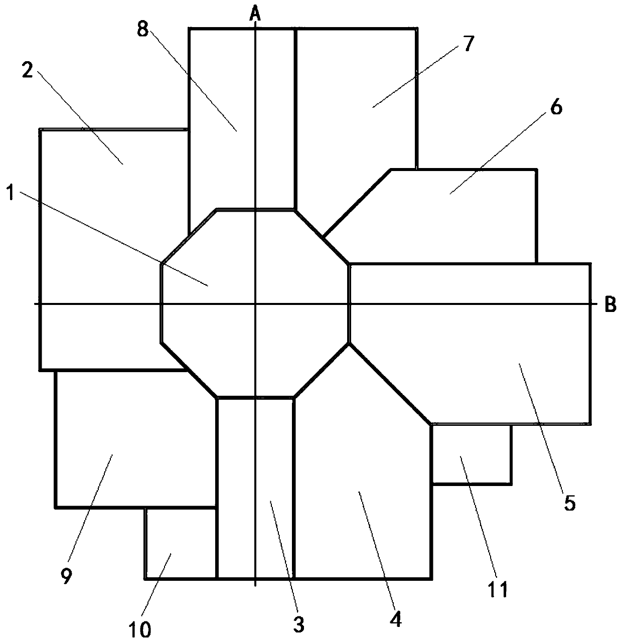
[0046] This embodiment discloses a method for arranging the main building group of a tokamak magnetic confinement fusion power station, such as figure 1 As shown, taking the tokamak plant 1 as the center, the neutral beam power plant 8, the magnet power plant 7, the heating plant 6, the auxiliary plant 5, the tritium plant 4, the heat chamber 3, the steam turbine plant 9 and the electrical plant 2 form a ring The shapes are arranged around the periphery of the tokamak plant 1.

[0047] Further, the neutral beam power plant 8 and the heat chamber 3 are respectively arranged on both sides of the tokamak plant 1 along the longitudinal axis of the tokamak plant 1 .

[0048] The electrical plant 2 and the auxiliary plant 5 are respectively arranged on both sides of the tokamak plant 1 along the direction of the transverse axis of the tokamak plant 1 .

[0049] The tritium plant 4 is arranged between the hot chamber 3 and the auxiliary plant 5 .

[0050] The heating plant 6 and th...

Embodiment 2

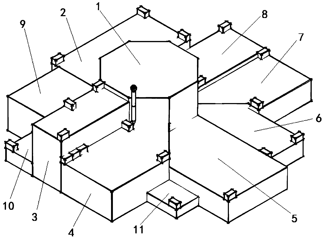
[0077] Such as figure 1 , figure 2 As shown, this embodiment discloses the structure of a main building group of a tokamak magnetic confinement fusion power station, including a tokamak building 1, a neutral beam power supply building 8, a magnet power supply building 7, a heating building 6, an auxiliary building 5, tritium Plant 4, heat chamber 3, steam turbine plant 9 and electrical plant 2, of which: tokamak plant 1 is located in the center of the main plant group, neutral beam power plant 8, magnet power plant 7, heating plant 6, auxiliary plant 5 , tritium plant 4, heat chamber 3, steam turbine plant 9 and electrical plant 2 are located on the periphery of tokamak plant 1.

[0078] Specifically, the tokamak plant 1 is located in the middle of the nuclear power plant. The height of the tokamak plant (both refer to the absolute height) is 70-90m, preferably 80m in this embodiment.

[0079] The neutral beam power plant 8 and the heat chamber 3 are respectively arranged ...


PUM


Abstract

The invention discloses an arranging method of a main workshop group of a Tokamak magnetically-confined fusion power station. The arranging method of the main workshop group of the Tokamak magnetically-confined fusion power station comprises the steps that a Tokamak workshop is taken as a center, and a neutral beam power-source workshop, a magnet power-source workshop, a heating workshop, an auxiliary workshop, a tritium workshop, a hot cell, a steam turbine workshop and an electric workshop are arranged in a ring shape around the periphery of the tokamak workshop. The invention further discloses a structure of the main workshop group of the Tokamak magnetically-confined fusion power station. The requirements of commercial nuclear power stations can be met, and the space utilization rate and safety of the nuclear power stations are improved.

Description

technical field [0001] The invention belongs to the field of nuclear engineering, and in particular relates to an arrangement method and structure of a main workshop group of a tokamak magnetic confinement fusion power station. Background technique [0002] According to the presence or absence of neutron moderators, reactors can be divided into two categories: thermal neutron reactors and fast neutron reactors. The nuclear power plants that have been built and are under construction are also designed and arranged mainly based on whether there is a neutron moderator in the reactor. [0003] Due to the limitations of nuclear fuel reserves and physical principles, nuclear fission power plants are difficult to support the sustainable development of human society, and there are certain potential dangers. Compared with nuclear fission, nuclear fusion has much less radioactive pollution, and its raw materials are almost inexhaustible. It is a more ideal energy source and has attra...

Claims


Application Information

Patent Timeline
Patent Type & Authority Applications(China)
IPC IPC(8): G21D1/00G21D1/02
CPCG21D1/00G21D1/02Y02E30/00
Inventor 谷振杰王振中薛静吴巧英贾小攀贝晨赵晓山
Owner CHINA NUCLEAR POWER ENG CO LTD
Why Eureka
Try Eureka