Suction and exhaust valve floating ball and suction and exhaust valve composed of floating ball

An intake and exhaust valve, floating ball technology, applied in the valve shell structure, valve operation/release device, lift valve and other directions, can solve problems such as failure to exhaust, poor reliability, and collapse of the pipeline system

Pending Publication Date: 2020-01-17
奎屯耐特阀门科技有限公司
View PDF2 Cites 0 Cited by
  • Summary
  • Abstract
  • Description
  • Claims
  • Application Information

AI Technical Summary

Problems solved by technology

[0005] The Chinese invention patent with the publication number of Chinese patent application CN104613207 A discloses a "pipe exhaust valve". The valve body is installed at the end of the drain pipe body. The water inlet and discharge port connected to the outside, the pipeline exhaust valve includes a gas collection device inside the valve body and a buoy exhaust device, the gas collection device is arranged at the bottom of the valve body, and the buoy exhaust device is located In the upper part of the device, although this pipeline exhaust valve can be designed to collect and exhaust gas, and there is an air-collecting ring inside the valve to concentrate and discharge the air bubbles in the water flow through the valve, but this exhaust valve us

Method used


Image

  • Suction and exhaust valve floating ball and suction and exhaust valve composed of floating ball
  • Suction and exhaust valve floating ball and suction and exhaust valve composed of floating ball
  • Suction and exhaust valve floating ball and suction and exhaust valve composed of floating ball

Examples


Embodiment 1

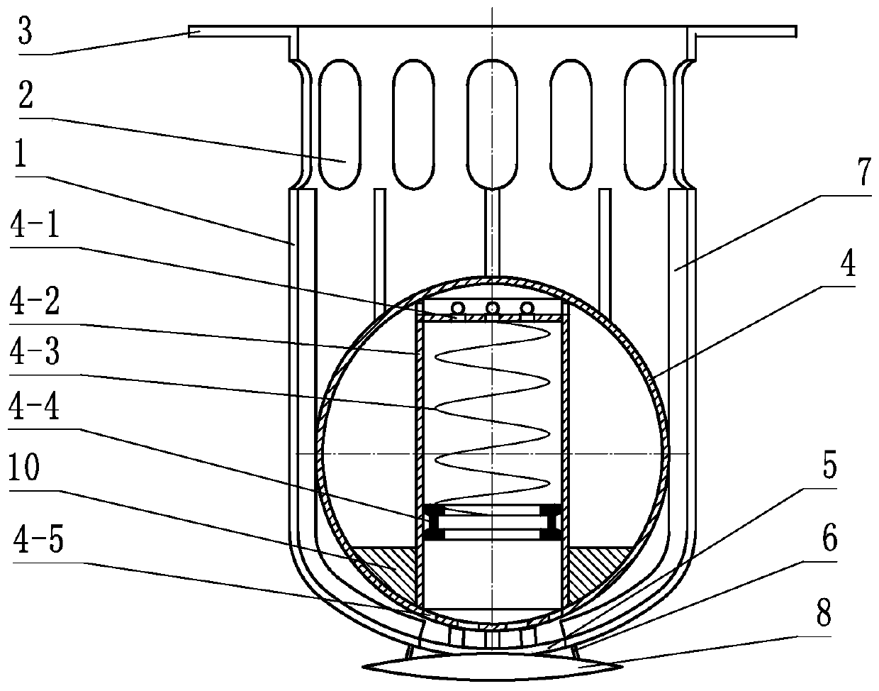
[0030] Embodiment 1: refer to figure 1 with 2 , is a structural schematic diagram of Embodiment 1 of the present invention, the intake and exhaust valve float includes a float housing 4, and the float housing 4 is provided with an adjustment mechanism that adapts to the external pressure. The piston-like mechanism in the inner cavity, the piston-like mechanism includes a piston cylinder 4-2 and a piston 4-4 in the piston cylinder 4-2, and the piston cylinder 4-2 inside the piston 4-4 is provided with an inner air hole 4- 1. Make the piston cylinder 4-2 inside the piston 4-4 communicate with the inner cavity of the float housing 4, and the piston cylinder 4-2 outside the piston 4-4 or the float housing 4 is provided with an outer air hole 4-5, Make the piston cylinder 4-2 outside the piston 4-4 communicate with the space outside the float housing 4. A counterweight 10 is preferably provided at the inner bottom of the floating ball housing 4, so that the stability of the float...

Embodiment 2

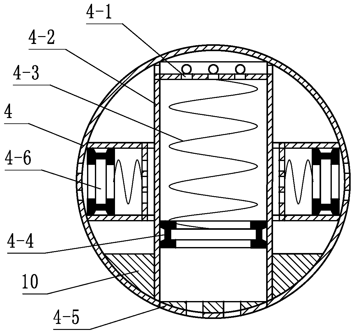
[0033] Embodiment 2: refer to image 3 , is a structural schematic diagram of Embodiment 2 of the present invention. Compared with Embodiment 1, the difference of Embodiment 2 is that several floating ball housings 4 outside the piston cylinder 4-2 are provided with several Around the auxiliary piston mechanism 4-6 outside the piston cylinder 4-2, the auxiliary piston mechanism 4-6 includes the inner air hole inside the piston cylinder, the piston, and the outer air hole 4-5 on the outer side of the piston. return spring.

Embodiment 3

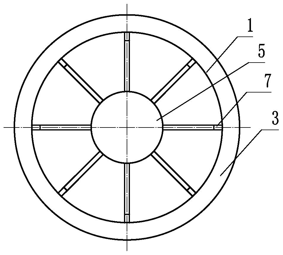
[0034] Embodiment 3: refer to Figure 4 , is a schematic structural view of Embodiment 3 of the present invention. Compared with the previous embodiments, the difference of this embodiment is that the rib 7 is a plurality of bends on the wall of the body of the floating ball outer barrel 1. .


PUM


Abstract

The invention discloses a suction and exhaust valve floating ball capable of being adjusted according to system pressure and a suction and exhaust valve composed of the floating ball. The suction andexhaust valve floating ball comprises a floating ball shell (4), an adjusting mechanism used for adapting to the outside pressure is arranged in the floating ball shell (4), and the adjusting mechanism is a piston-shaped mechanism or a balloon-shaped mechanism in an inner cavity of the floating ball shell (4). Compared with the prior art, the suction and exhaust valve floating ball can be adjustedaccording to the system pressure, adapts to change of the pressure in a conveying pipeline to a certain extent, and it is ensured that the conveying pipeline is safe and smooth.

Description

technical field [0001] The invention relates to a floating ball of an intake and exhaust valve and the formed intake and exhaust valve. Background technique [0002] There is often air inside the water pipeline, and under the joint action of water flow and air flow, pipe bursts often occur, especially in the transmission system with long pipelines and large slope fluctuations, multiple undulations of the pipeline often occur. In this case, if there is a water stop or gas accumulation in the pipeline, the water flow will be poor or even the water will be cut off. [0003] In addition, many water pipelines use PVC pipes. When the water is too large, due to the negative pressure in the pipes, it is easy to flatten the pipes, deform or rupture. These are prone to large-scale water cutoffs, which not only affect the People's normal life also consumes a lot of manpower and material resources for emergency repairs, which has brought great problems to the normal water supply. [0...

Claims


Application Information

Patent Timeline
IPC IPC(8): F16K31/20F16K1/36F16K1/32F16K27/02F16K27/12
CPCF16K1/32F16K1/36F16K27/02F16K27/12F16K31/20
Inventor 隋春升
Owner 奎屯耐特阀门科技有限公司
Why Eureka
Try Eureka