Molten salt conveying system for solar photo-thermal power station
What is AI technical title?
AI technical title is built by PatSnap AI team. It summarizes the technical point description of the patent document.
A technology of solar energy and power stations, applied in the field of molten salt delivery system, can solve the problems of rising production cost, long delivery cycle and high price of molten salt
Inactive Publication Date: 2020-01-17
ZHEJIANG SUPCON SOLAR TECHNOLOGY CO LTD
View PDF12 Cites 3 Cited by
Summary
Abstract
Description
Claims
Application Information
AI Technical Summary
This helps you quickly interpret patents by identifying the three key elements:
Problems solved by technology
Method used
Benefits of technology
Problems solved by technology
However, due to the limitation of the use of the vertical long-axis submerged molten salt pump, two problems have been caused: one of the problems is that due to the limitation of the use of the vertical long-axis submerged molten salt pump, the high temperature molten salt storage tank and the low temperature There is a large amount of molten salt in the molten salt storage tanks that cannot be used, resulting in an increase in the purchase cost of molten salt and the production cost of the storage tank. According to a tower-type solar thermal power station with a scale of 100MW heat storage for 12 hours, the amount of molten salt that cannot be used is about 6000t. Therefore, the height of the salt storage tank has to be increased by 1m, resulting in a cost of as much as 20 million to 30 million; the second problem is that the design and manufacture of vertical long-axis submerged molten salt pumps are difficult, and currently the world's production There are only a handful of manufacturers of long-axis molten salt pumps used in tower-type solar power plants, and they are expensive and have a long delivery cycle. In addition, the shaft of the vertical long-axis submerged pump is composed of multiple stages and is 16m or even 18m long. , The hoisting requirements are high, and the bearing bushes located in the submerged part need to be replaced regularly, and the maintenance time can be as long as half a month. The potential operation and maintenance costs and operation risks are high, which is not conducive to the development of solar thermal power generation industry
[0007] Although the above invention avoids the use of a vertical long-axis submerged molten salt pump, this invention does not solve the problem of rising costs caused by the large amount of unusable salt, and does not eliminate the unsafe factors caused by the combination of high and low tanks
[0008] Therefore, looking for a safe solution can not only properly solve the cost, operation and maintenance cost increase and potential operation safety risks brought by the vertical long-axis submerged molten salt pump, but also avoid the existence of large and small tanks or high and low tanks. potential safety hazard is the problem to be solved in this patent
Method used
Image
Click on the blue label to locate the original text in one second.
Reading with bidirectional positioning of images and text.
Examples
Embodiment 1
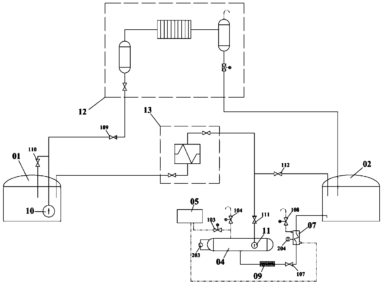
[0050] as attached figure 1 As shown, a molten salt delivery system for a solar thermal power station includes: a high-level tank system, a molten salt heat absorption subsystem 12, a molten salt heat exchange subsystem 13, and a molten salt transmission subsystem;
[0051] The high-level tank system includes: low-temperature molten salt storage tank 01, high-temperature molten salt storage tank 02;
[0052] The molten salt transmission subsystem includes a high temperature molten salt transmission subsystem.
[0053] The high-temperature molten salt transmission subsystem is set corresponding to the high-temperature molten salt storage tank 02; the high-temperature molten salt transmission subsystem includes a high-temperature molten salt low-level tank 04; the installation height of the high-temperature molten salt low-level tank 04 is lower than the The high-temperature molten salt storage tank 02; the volume of the high-temperature molten salt low-level tank 04 is smaller...
Embodiment 2
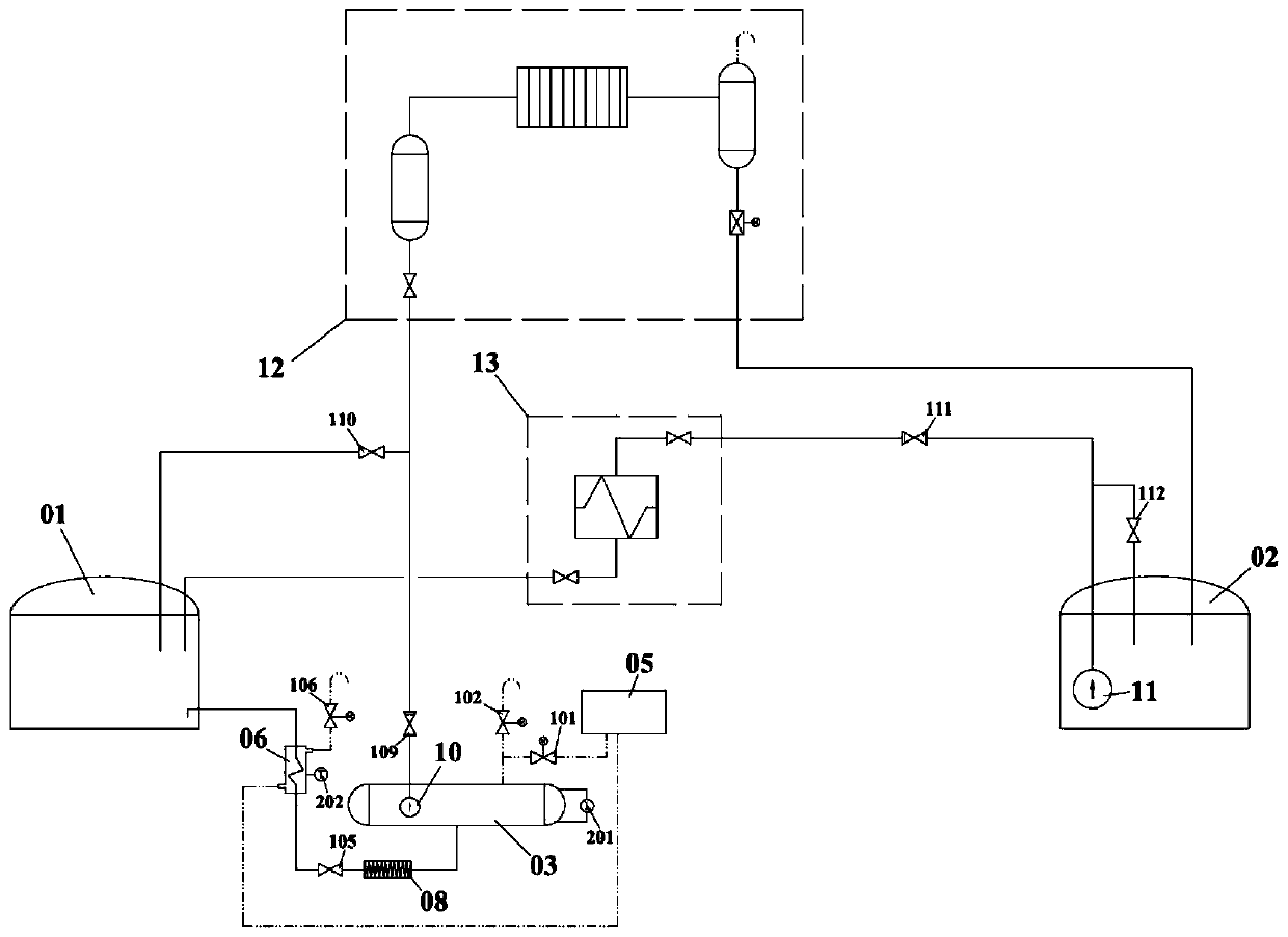
[0078] as attached figure 2 As shown, a molten salt delivery system for a solar thermal power station includes: an elevated tank system, a molten salt heat absorption subsystem 12, a molten salt heat exchange subsystem 13, and a molten salt transmission subsystem.
[0079] The high-level tank system includes: low-temperature molten salt storage tank 01, high-temperature molten salt storage tank 02;
[0080] The molten salt transmission subsystem includes a low temperature molten salt transmission subsystem.
[0081] The low-temperature molten salt transmission subsystem is set corresponding to the low-temperature molten salt storage tank 01; the low-temperature molten salt transmission subsystem includes a low-temperature molten salt low-level tank 03; the installation height of the low-temperature molten salt low-level tank 03 is lower than the The low-temperature molten salt storage tank 01; the volume of the low-temperature molten salt low-level tank 03 is smaller than th...
Embodiment 3
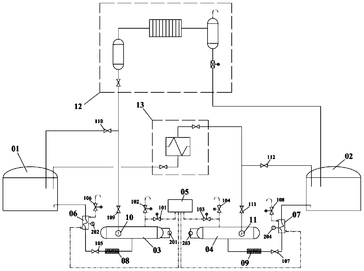
[0108] as attached image 3 As shown, a molten salt delivery system for a solar thermal power station includes: a high-level tank system, a molten salt heat absorption subsystem 12, a molten salt heat exchange subsystem 13, and a molten salt transmission subsystem;
[0109] The high-level tank system includes: low-temperature molten salt storage tank 01, high-temperature molten salt storage tank 02;
[0110] The molten salt transmission subsystem includes a high temperature molten salt transmission subsystem and a low temperature molten salt transmission subsystem.
[0111]The high-temperature molten salt transmission subsystem is set corresponding to the high-temperature molten salt storage tank 02; the high-temperature molten salt transmission subsystem includes a high-temperature molten salt low-level tank 04; the installation height of the high-temperature molten salt low-level tank 04 is lower than the The high-temperature molten salt storage tank 02; the volume of the h...
PUM
Abstract
The invention provides a molten salt conveying system for a solar photo-thermal power station. The molten salt conveying system comprises a molten salt heat absorption subsystem, a molten salt heat exchange subsystem, a high-position tank subsystem comprising a high-temperature molten salt storage tank and a low-temperature molten salt storage tank and a molten salt transmission subsystem; the molten salt transmission subsystem includes a high-temperature molten salt transmission subsystem and / or a low-temperature molten salt transmission subsystem; the high-position tank subsystem is connected to the molten salt transmission subsystem; the high-temperature molten salt transmission subsystem includes a high-temperature molten salt low-position tank; the installation height of the high-temperature molten salt low-position tank is smaller than that of the high-temperature molten salt storage tank; the volume of the high-temperature molten salt low-position tank is smaller than the volumeof the high-temperature molten salt storage tank; the low-temperature molten salt transmission subsystem includes a low-temperature molten salt low-position tank; the installation height of the low-temperature molten salt low-position tank is lower than that of the low-temperature molten salt storage tank; and the volume of the low-temperature molten salt low-position tank is smaller than the volume of the low-temperature molten salt storage tank. The molten salt conveying system solves the problems about construction cost, operation and maintenance cost and the like caused by using a vertical long-axis submerged molten salt pump, and hidden safety hazards in design of large and small tanks or high and low tanks are avoided.
Description
technical field [0001] The invention belongs to the field of solar thermal power generation, and in particular relates to a molten salt delivery system used in a solar thermal power station. Background technique [0002] There are various ways to utilize solar energy, including wind energy, tidal energy, photovoltaic power generation, solar thermal power generation and other technical categories. Solar thermal power generation can be divided into trough type, tower type, butterfly type and linear Fresnel according to the structure of concentrating mirror and heat collector. [0003] In order for solar thermal technology to stand out among many power generation technologies and ultimately achieve a major breakthrough in cost, at least two problems need to be solved, one is the reliability of the equipment, and the other is to optimize the system structure through process improvement. Reduce equipment investment. [0004] Whether it is based on trough, tower, butterfly, or l...
Claims
Application Information
Patent Timeline
Application Date:The date an application was filed.
Publication Date:The date a patent or application was officially published.
First Publication Date:The earliest publication date of a patent with the same application number.
Issue Date:Publication date of the patent grant document.
PCT Entry Date:The Entry date of PCT National Phase.
Estimated Expiry Date:The statutory expiry date of a patent right according to the Patent Law, and it is the longest term of protection that the patent right can achieve without the termination of the patent right due to other reasons(Term extension factor has been taken into account ).
Invalid Date:Actual expiry date is based on effective date or publication date of legal transaction data of invalid patent.

