
Method and system for positioning disturbance signal of optical fiber distributed disturbance sensing system

An optical fiber distribution, sensing system technology, applied in the direction of using optical devices to transmit sensing components, character and pattern recognition, instruments, etc., can solve the problems of low false alarm rate, increase system complexity, increase system cost, etc.

Inactive Publication Date: 2020-01-17
南京申威光电技术研究院有限公司
View PDF7 Cites 7 Cited by
  • Summary
  • Abstract
  • Description
  • Claims
  • Application Information

AI Technical Summary

Problems solved by technology

[0003] The sensing distance of the traditional Φ-OTDR optical fiber distributed disturbance sensing system can only reach about 26km. Due to the limitation of nonlinear effects, it is difficult to achieve long-distance monitoring and low false alarm rate.
In order to improve the sensing distance, the existing solutions not only increase the system cost but also increase the complexity of the system by introducing new amplification technology.
In order to reduce the false alarm rate, Empirical Mode Decomposition (EMD) and wavelet threshold denoising method are usually used, and the EMD denoising method discards some high-frequency components from the decomposed components. At the same time, part of the useful information in the high frequency band is also lost together, which may lead to serious distortion of the useful signal; the wavelet threshold noise reduction method also has the same defect, while discarding the noise signal, it also discards the useful signal together, so how to effectively It is particularly important to remove the noise signal and reduce the distortion of the real signal to achieve longer distance monitoring and reduce the false alarm rate

Method used


Image

  • Method and system for positioning disturbance signal of optical fiber distributed disturbance sensing system
  • Method and system for positioning disturbance signal of optical fiber distributed disturbance sensing system
  • Method and system for positioning disturbance signal of optical fiber distributed disturbance sensing system

Examples


Embodiment Construction

[0027] The present invention will be further described below in conjunction with embodiment, but protection scope of the present invention is not limited to this:

[0028] combine figure 1 , is the structure diagram of the Φ-OTDR optical fiber distributed disturbance sensing system applied in the present invention, and is also a traditional structure, which includes a light source, a pulsed light modulator, an erbium-doped fiber amplifier, a circulator, a sensing fiber, a photodetector, Data acquisition and processing unit. On the basis of the system, the present invention does not introduce other optical amplification technologies to increase the complexity and cost of the system structure, and only realizes long-distance monitoring and better noise reduction effects by changing the subsequent signal processing and noise reduction methods, reducing the False alarm rate.

[0029] The data acquisition and processing unit of the present invention is used to perform the followi...


PUM


Abstract

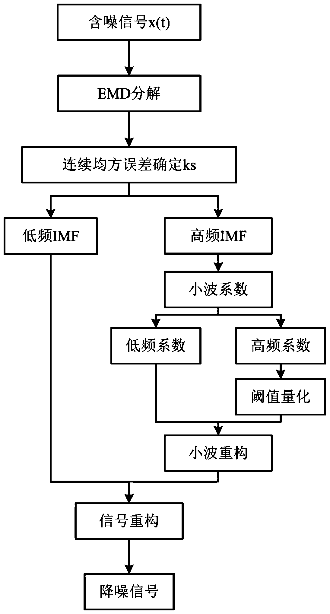
The invention discloses a method for positioning a disturbance signal of an optical fiber distributed disturbance sensing system. The method comprises the following steps of: S1, performing noise reduction processing on backward Rayleigh scattering light by using a wavelet threshold noise reduction method of EMD to obtain a noise reduction signal; S2, performing segmentation processing according to the overall level of the data acquired by the system, and determining alarm thresholds of different distance range segments; and S3, positioning a disturbance event according to the noise reductionsignal obtained in the step S1 and the alarm threshold set in the step S2. On the basis of not introducing other technologies into the system, a long monitoring distance and a low false alarm rate areachieved. The method is simple in process, easy to implement, low in cost and suitable for practical application.

Description

technical field [0001] The invention belongs to the field of optical fiber distributed disturbance sensors, and in particular relates to a signal processing method of a Φ-OTDR optical fiber distributed disturbance sensing system based on an EMD wavelet threshold noise reduction method and a segmented threshold method. Background technique [0002] The optical fiber distributed optical fiber sensing system based on the phase-sensitive optical time domain reflectometer (Φ-OTDR) uses pulsed light with narrow linewidth and low frequency drift, and detects the back Rayleigh scattering generated in the optical fiber within a fixed pulse width through a photodetector. Light, after subsequent data processing, achieves the monitoring and positioning of the disturbance position. [0003] The sensing distance of the traditional Φ-OTDR optical fiber distributed disturbance sensing system can generally only reach about 26km. Due to the limitation of nonlinear effects, it is difficult to ...

Claims


Application Information

Patent Timeline
Patent Type & Authority Applications(China)
IPC IPC(8): G01D5/353G06K9/00
CPCG01D5/353G06F2218/06
Inventor 张春熹马福马皓钰王夏霄刘海霞宋镜明
Owner 南京申威光电技术研究院有限公司
Learn More