Laser beam orientation measuring device and method

A technology of laser beam and measuring device, applied in the field of laser beam pointing measuring device, can solve problems such as inability to measure flat drift, and achieve the effects of reducing structural difficulty, realization difficulty and measurement error, and avoiding errors

Active Publication Date: 2020-01-17
TECH & ENG CENT FOR SPACE UTILIZATION CHINESE ACAD OF SCI
View PDF5 Cites 4 Cited by
  • Summary
  • Abstract
  • Description
  • Claims
  • Application Information

AI Technical Summary

Problems solved by technology

The direction of the incident beam contains four dimensions of information, including up/down translation, left/right translation, incide

Method used


Image

  • Laser beam orientation measuring device and method
  • Laser beam orientation measuring device and method
  • Laser beam orientation measuring device and method

Examples


Embodiment Construction

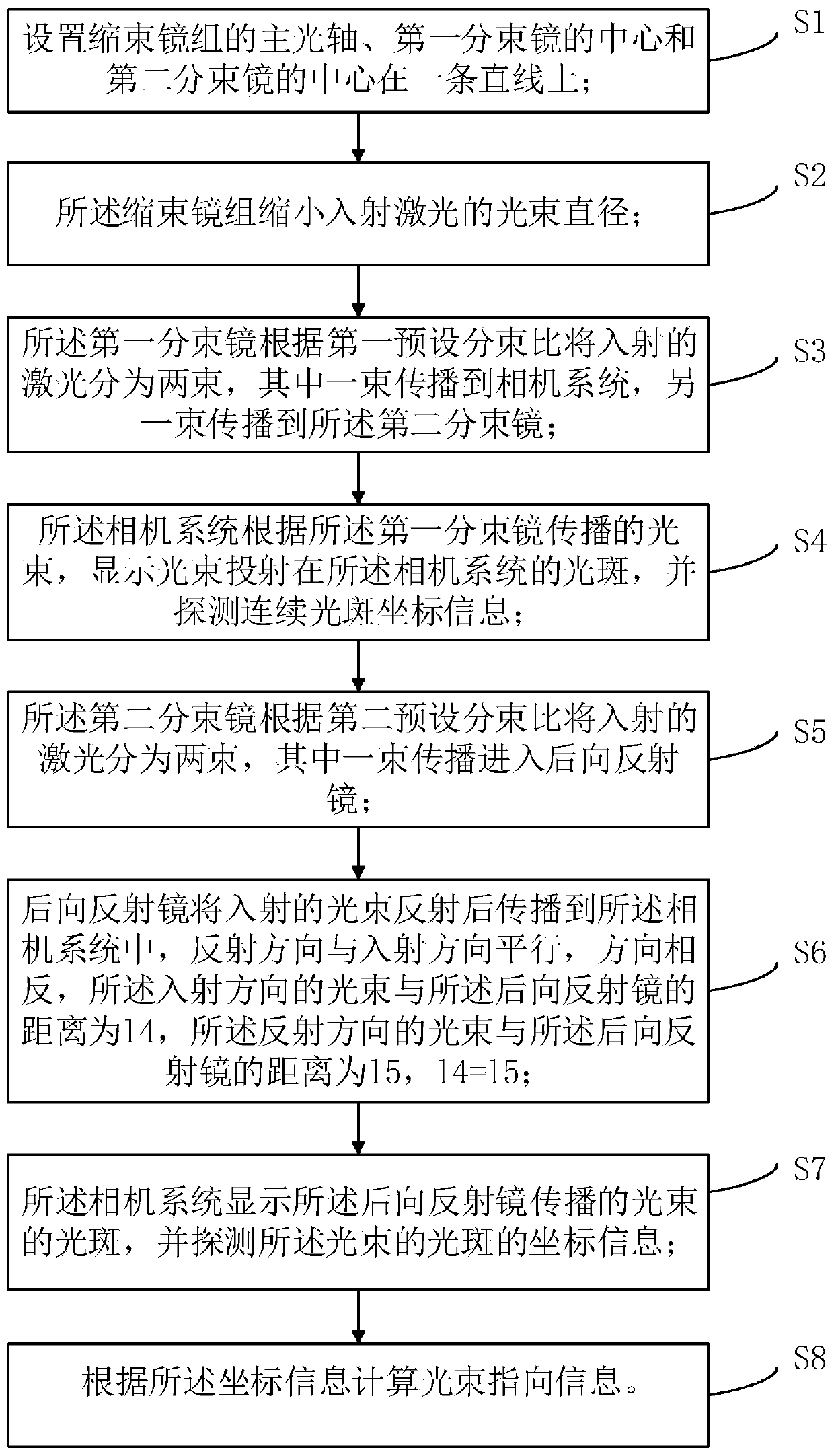
[0105] The principles and features of the present invention will be described below in conjunction with the accompanying drawings, and the examples given are only used to explain the present invention, and are not intended to limit the scope of the present invention.

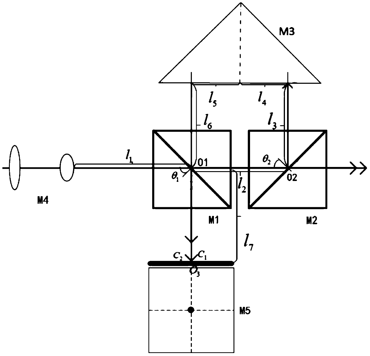
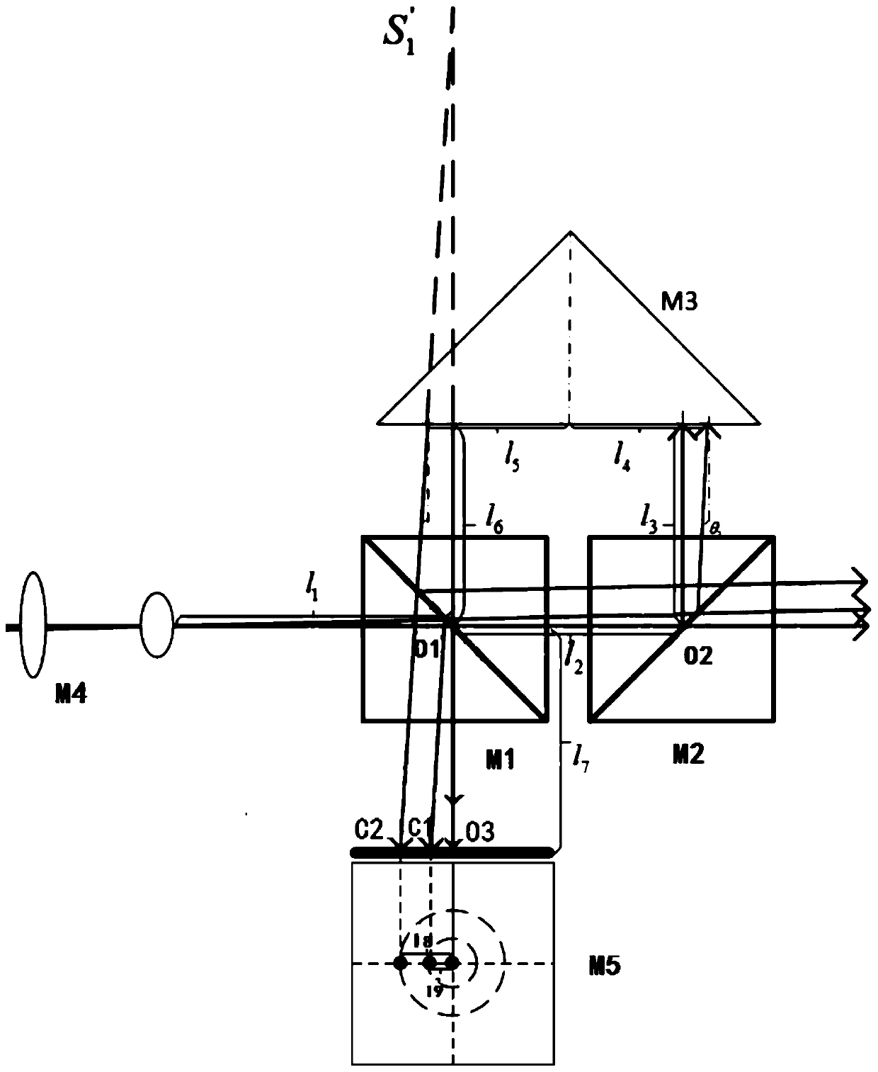
[0106] Such as figure 1 As shown, a laser beam pointing measurement device provided by an embodiment of the present invention, the device includes: a beam reducing mirror group M4, a first beam splitting mirror M1, a second beam splitting mirror M2, a retroreflector M3 and a camera system M5; the main optical axis of the beam reducer group M4, the center of the first beam splitter M1 and the center of the second beam splitter M2 are on a straight line;

[0107] The distance between the exit surface of the beam reducer group M4 and the center of the first beam splitter M1 is l1; the center of the first beam splitter M1 and the center of the second beam splitter M2 are on a straight line, and the distance between ...


PUM


Abstract

The invention relates to a laser beam orientation measuring device and method, and relates to the field of laser beam orientation measuring. The device comprises a beam shrinking lens group M4, a first beam splitter M1, a second beam splitter M2, a backward reflecting mirror M3 and a camera system M5; the primary optical axis of the beam shrinking lens group, the center of the first beam splitterM1 and the center of the second beam splitter M2 are in a straight line; and light spots of incident laser are detected and displayed through the device, the beam orientation is calculated according to coordinate information of continuous light spots, and angle drifts and translation drifts can be calculated simultaneously. Meanwhile, a reflecting mirror is not used, so that errors brought by imprecise adjustment of the reflecting mirror are avoided; and a focusing lens is not used, so that errors brought by the facts that the optical axis is not aligned and a camera cannot be accurately placed at the focus are avoided.

Description

technical field [0001] The invention relates to the field of laser beam pointing measurement, in particular to a laser beam pointing measurement device and method. Background technique [0002] In the existing device for measuring beam pointing angle information, the measured beam is usually incident on the center of the detection surface of the image acquisition unit after passing through the f-theta field lens and the light intensity regulator. The detection surface of the image acquisition unit is located in the f-theta field On the back focal plane of the mirror, the laser spot emitted by the laser under test is obtained. Then the host computer calculates the angle information of the laser beam pointing stability according to the image information collected by the image acquisition unit. The two-dimensional translation stage is used to adjust the camera position so that the center of the camera is aligned with the optical axis of the field lens. The direction of the in...

Claims


Application Information

Patent Timeline
IPC IPC(8): G01J1/00
CPCG01J1/00
Inventor 展月英熊建张春晖熊蛟石紫元孙扬
Owner TECH & ENG CENT FOR SPACE UTILIZATION CHINESE ACAD OF SCI
Why Eureka
Try Eureka