High-protection-level air-cooled lithium battery pack thermal management system and method

A thermal management system and management system technology, applied in the field of air-cooled lithium battery pack thermal management systems, can solve the problems of low heat dissipation efficiency, great safety hazard, and large battery damage, achieve high heat dissipation efficiency, prevent exchange pollution, and avoid liquid The effect of pollution

Pending Publication Date: 2020-01-17
赵耀华 +1
View PDF12 Cites 1 Cited by
  • Summary
  • Abstract
  • Description
  • Claims
  • Application Information

AI Technical Summary

Problems solved by technology

[0007] In order to solve the problems of the existing technology, such as large potential safety hazards, low heat dissipation efficiency, great damage to the battery, no energy saving, and the inability to use it in the parking state, the present invention proposes a high protection level air-cooled lithium battery pack thermal management system and method

Method used


Image

  • High-protection-level air-cooled lithium battery pack thermal management system and method
  • High-protection-level air-cooled lithium battery pack thermal management system and method
  • High-protection-level air-cooled lithium battery pack thermal management system and method

Examples


Embodiment 1

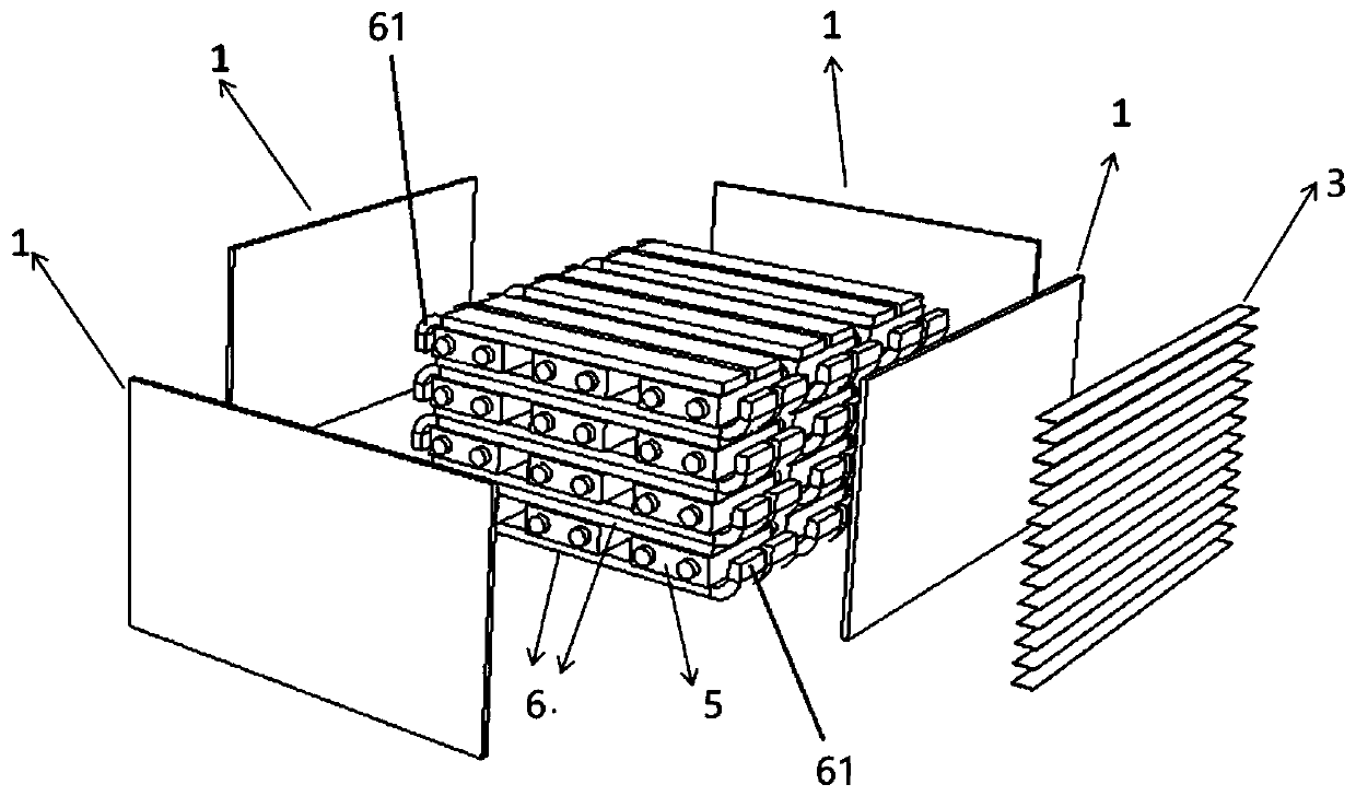
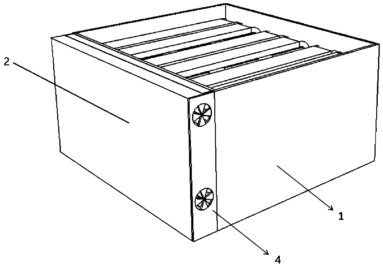
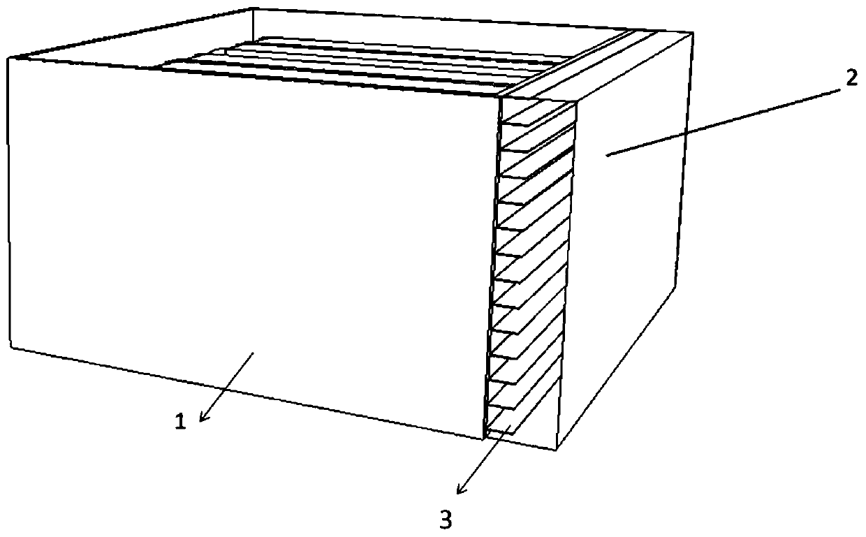
[0040] Such as Figure 1-3 As shown, an air-cooled lithium battery pack thermal management system with a high protection level in this embodiment includes horizontal cells in the battery pack and an external air-cooling module 2 attached to the outside of the battery pack shell 1. The air-cooling module includes a fan 4 and air-cooling fins 3. The battery cells in the battery pack are divided into four layers, each layer has three vertically and three horizontally. The upper and lower surfaces of the three battery units 5 in each horizontal layer are attached to two sets of micro heat pipe arrays 6 extending in the lateral direction. The micro heat pipe array 6 is a flat heat conductor with a porous structure formed by extrusion of a metal material, and has a plurality of micro heat pipes arranged side by side that are not connected to each other and operate independently, and the hydraulic diameter of each micro heat pipe is 1mm. The internal phase change working medium is ...

Embodiment 2

[0048] In order to ensure that the temperature difference between the air inlet and outlet of the air-cooling module is small, so that the temperature difference of all batteries is not higher than 5°C, the air duct of the air-cooling module in this embodiment is a static pressure box, as shown in Figure 5 As shown, other structures and working methods are similar to Embodiment 1.

Embodiment 3

[0050] The internal structure of the battery of this embodiment is as Figure 6 As shown, only the lower side has the micro heat pipe array, both sides have the protruding part 61 and are bent upwards, and other structures and principles are consistent with the first embodiment.


PUM

PropertyMeasurementUnit
diameteraaaaaaaaaa

Abstract

The invention discloses a high-protection-level air-cooled lithium battery pack thermal management system and method. The system comprises one or more layers of batteries and / or battery modules in thebattery pack, a battery pack shell and an external air cooling module, wherein the battery and / or the upper surface and / or the lower surface are / is attached to a micro heat pipe array, the part attached to the surface of the battery and / or the battery module is an evaporation section, at least one end of the micro heat pipe array extends out of the surface of the battery and / or the battery module, and the extending part serves as a condensation section to be attached to a battery pack shell; the battery pack shell surrounds the battery pack and is of a closed structure, and at least the position, corresponding to the condensation section, of the battery pack shell is provided with a heat conduction partition plate; the external air cooling module is tightly attached to the outer surface of the face, provided with the heat conduction partition plate, of the battery pack shell, air cooling fins are arranged in the external air cooling module, and a fan is arranged on the side face of the external air cooling module. The heat dissipation efficiency is high, the risk of liquid pollution is avoided, and the protection level is high.

Description

technical field [0001] The invention relates to an air-cooled lithium battery pack thermal management system and method with a high protection level, belonging to the field of battery pack heat dissipation for electric vehicles. Background technique [0002] The thermal management of lithium battery packs is not only critical to battery life, but also critical to battery safety. [0003] The traditional battery pack thermal management method - air cooling technology not only cannot meet the requirements of the protection level of the lithium battery pack, but also due to the large temperature difference between the inlet and outlet of the air cooling system, resulting in a large temperature difference between the battery cell and the battery cell, which is harmful to the lithium battery. The damage is large, so it is basically useless at present. [0004] The traditional thermal management method of lithium battery packs with high protection level generally adopts the liqui...

Claims


Application Information

Patent Timeline
Patent Type & Authority Applications(China)
IPC IPC(8): H01M2/10H01M10/613H01M10/615H01M10/625H01M10/6551H01M10/6552H01M10/6563H01M10/657B60L58/26B60L58/27
CPCH01M10/613H01M10/615H01M10/625H01M10/6551H01M10/6552H01M10/6563H01M10/657B60L58/26B60L58/27H01M2220/20H01M50/20Y02T10/70Y02E60/10
Inventor 赵耀华徐红霞
Owner 赵耀华
Why Eureka
Try Eureka