Vehicle-mounted charging and discharging system and control method

A charge-discharge and controller technology, applied in battery/fuel cell control devices, charging stations, control/regulation systems, etc., can solve the impact of system conversion efficiency and reliability, poor cross-regulation rate of on-board charge-discharge systems, difficult Implement soft switching and other issues

Active Publication Date: 2020-01-17
HUAWEI DIGITAL POWER TECH CO LTD
View PDF4 Cites 2 Cited by
  • Summary
  • Abstract
  • Description
  • Claims
  • Application Information

AI Technical Summary

Problems solved by technology

figure 2 The vehicle-mounted charge-discharge system shown uses a three-port second converter, which can reduce the volume of the vehicle-mounted charge-discharge system to a certain extent and reduce production costs, but the multi-o...

Method used


Image

  • Vehicle-mounted charging and discharging system and control method
  • Vehicle-mounted charging and discharging system and control method
  • Vehicle-mounted charging and discharging system and control method

Examples


Embodiment 1

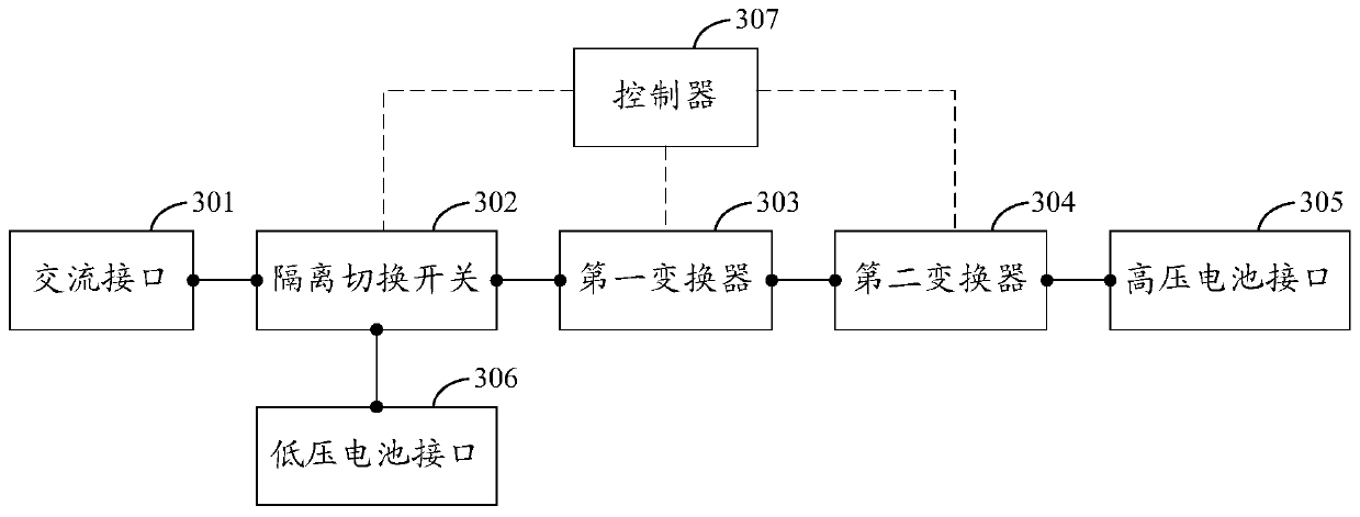
[0054] see image 3 , image 3 It is a schematic structural diagram of the on-board charging and discharging system provided by the embodiment of the present application. Such as image 3 As shown, the vehicle charging and discharging system includes: an AC interface 301 , an isolation switch 302 , a first converter 303 , a second converter 304 , a high voltage battery interface 305 , a low voltage battery interface 306 and a controller 307 .

[0055] The AC interface 301 is used to connect an AC power source or an AC load. Wherein, the AC power supply can be an external power supply for charging electric vehicles, such as charging piles, etc. When the AC power supply is connected to the AC interface 301, the controller 307 can control the isolation switch 302, the first converter 303 and the second converter The controller 304 controls the AC power supply to supply power to the high-voltage battery connected to the high-voltage battery interface 305 . The AC load can be a...

Embodiment 2

[0074] see Figure 8 , Figure 8 It is a schematic diagram of a circuit structure of an exemplary on-vehicle charging and discharging system provided in the embodiment of the present application.

[0075] Such as Figure 8 As shown, the first switch S1 is used as an isolation switch in the vehicle charging and discharging system; one end of the AC interface AC is connected to the first moving contact (contact 1) of the first switch S1, and the other end of the AC interface AC is connected to the first The first port of the converter 303; the positive terminal of the low-voltage battery interface LV BAT is connected to the second movable contact (contact 2) of the first switch S1, and the negative terminal of the low-voltage battery interface LV BAT is grounded. Normally, the low-voltage battery interface The negative port of the LV BAT can be grounded together with the first converter 303 ; the static contact (contact 3 ) of the first switch S1 is connected to the first port...

Embodiment 3

[0105] see Figure 9 , Figure 9 It is a schematic circuit diagram of another exemplary on-vehicle charging and discharging system provided in the embodiment of the present application.

[0106] Such as Figure 9 As shown, the isolation switch in the vehicle charging and discharging system may specifically include: a first switch S1 and a second switch S2. One end of the AC interface AC is connected to the first movable contact (contact 1) of the first switch S1, and the other end of the AC interface AC is connected to the first movable contact (contact 1*) of the second switch S2; the low-voltage battery interface LV The positive port of the BAT is connected to the common point M, which is the connection point between the second movable contact (contact 2) of the first switch S1 and the second movable contact (contact 2*) of the second switch S2; The negative terminal of the low-voltage battery interface LV BAT is grounded. Normally, the negative terminal of the low-voltag...


PUM


Abstract

The embodiment of the invention discloses a vehicle-mounted charging and discharging system and method, wherein the system comprises an AC interface, an isolation change-over switch, a first converter, a second converter, a high-voltage battery interface, a low-voltage battery interface and a controller. The controller is used for controlling the isolation change-over switch to be switched to a first conduction state so as to conduct the alternating-current interface with the high-voltage battery interface through the first converter and the second converter which are connected in series, controlling the first converter to work in a PFC mode or an inversion mode and controling the second converter to work in a DCDC isolation conversion mode, and the controller is also used for controllingthe isolation change-over switch to be switched to a second conduction state so as to conduct the low-voltage battery interface with the high-voltage battery interface through the first converter andthe second converter which are connected in series, controlling the first converter to work in the DCDC conversion mode, and controlling the second converter to work in the DCDC isolation conversion mode. According to the present invention, the size of the vehicle-mounted charging and discharging system can be reduced.

Description

technical field [0001] The present application relates to the technical field of electric vehicles, in particular to a vehicle charging and discharging system and a control method. Background technique [0002] With the continuous enhancement of people's awareness of environmental protection, electric vehicles are now favored by more and more consumers, and the research and development of electric vehicles has gradually become the focus of attention in the automotive industry. With the continuous development of electric vehicles, higher and higher requirements are put forward for the on-board charging and discharging system. It is hoped that the volume of the on-board charging and discharging system can be reduced, and the production cost of the on-board charging and discharging system can be reduced. [0003] At present, the more common on-board charging and discharging systems include: figure 1 and figure 2 Two structures are shown. exist figure 1 In the vehicle-mount...

Claims


Application Information

Patent Timeline
IPC IPC(8): H02J7/02H02J7/00H02M7/797H02M3/335B60R16/033
CPCH02J7/02H02M7/797H02M3/33576H02M3/33523B60R16/033H02M3/33584H02M3/01H02M1/10H02M1/007H02M1/4233H02M3/155H02J1/082H02J7/0013H02J7/342H02J2207/20H02J2310/48H02J3/322B60L58/20B60L53/22B60L2210/10
Inventor 刘卫平崔兆雪梁永涛
Owner HUAWEI DIGITAL POWER TECH CO LTD
Why Eureka
Try Eureka