
Steel pipe machining device based on PLC control

A technology for processing equipment and steel pipes, which is applied in the field of steel pipe processing equipment based on PLC control, can solve the problems of reduced production efficiency, complicated installation and disassembly, and shaking of steel pipes, and achieve the effects of improving production efficiency, improving drilling accuracy, and avoiding shaking

Inactive Publication Date: 2020-01-21
COLLEGE OF APPLIED SCI JIANGXI UNIV OF SCI & TECH
View PDF9 Cites 3 Cited by
  • Summary
  • Abstract
  • Description
  • Claims
  • Application Information

AI Technical Summary

Problems solved by technology

This technical solution cannot be positioned well when fixing the steel pipe, and there are errors, resulting in low machining accuracy, complicated installation and disassembly, and reduced production efficiency
This technical solution only fixes the steel pipe from one end, which is likely to cause the steel pipe to shake and cause large processing errors
[0004] In the application number: 201821617910.4, an equidistant drilling machine for copper pipe processing is disclosed, which includes a base plate and a drill rod. A motor is fixedly connected to one side of the top of the base plate, and the output shaft of the motor is fixedly connected to a threaded rod through a coupling. The other side of the bottom plate top is fixedly connected with a fixed plate, and the end of the threaded rod away from the motor is rotationally connected with one side of the fixed plate through a bearing. The surface of the threaded rod is threaded with a first threaded sleeve, and the bottom of the first threaded sleeve is fixedly connected with a slider, this technical solution also cannot effectively position the steel pipe, and the drilling accuracy is low

Method used


Image

  • Steel pipe machining device based on PLC control
  • Steel pipe machining device based on PLC control
  • Steel pipe machining device based on PLC control

Examples


Embodiment Construction

[0050] It should be noted that, in the case of no conflict, the embodiments in the present application and the features in the embodiments can be combined with each other; the technical solutions in the embodiments of the present invention will be described below in conjunction with the drawings in the embodiments of the present invention Clearly and completely described, it is obvious that the described embodiments are only some of the embodiments of the present invention, not all of them. Based on the embodiments of the present invention, all other embodiments obtained by persons of ordinary skill in the art without making creative efforts belong to the protection scope of the present invention.

[0051] In the description of the present invention, it should be understood that the orientation or positional relationship indicated by the terms "upper", "lower", "front", "rear", "left" and "right" are based on those shown in the accompanying drawings. Orientation or positional ...


PUM


Abstract

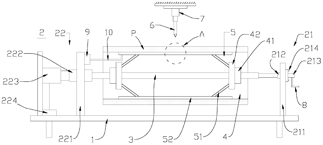
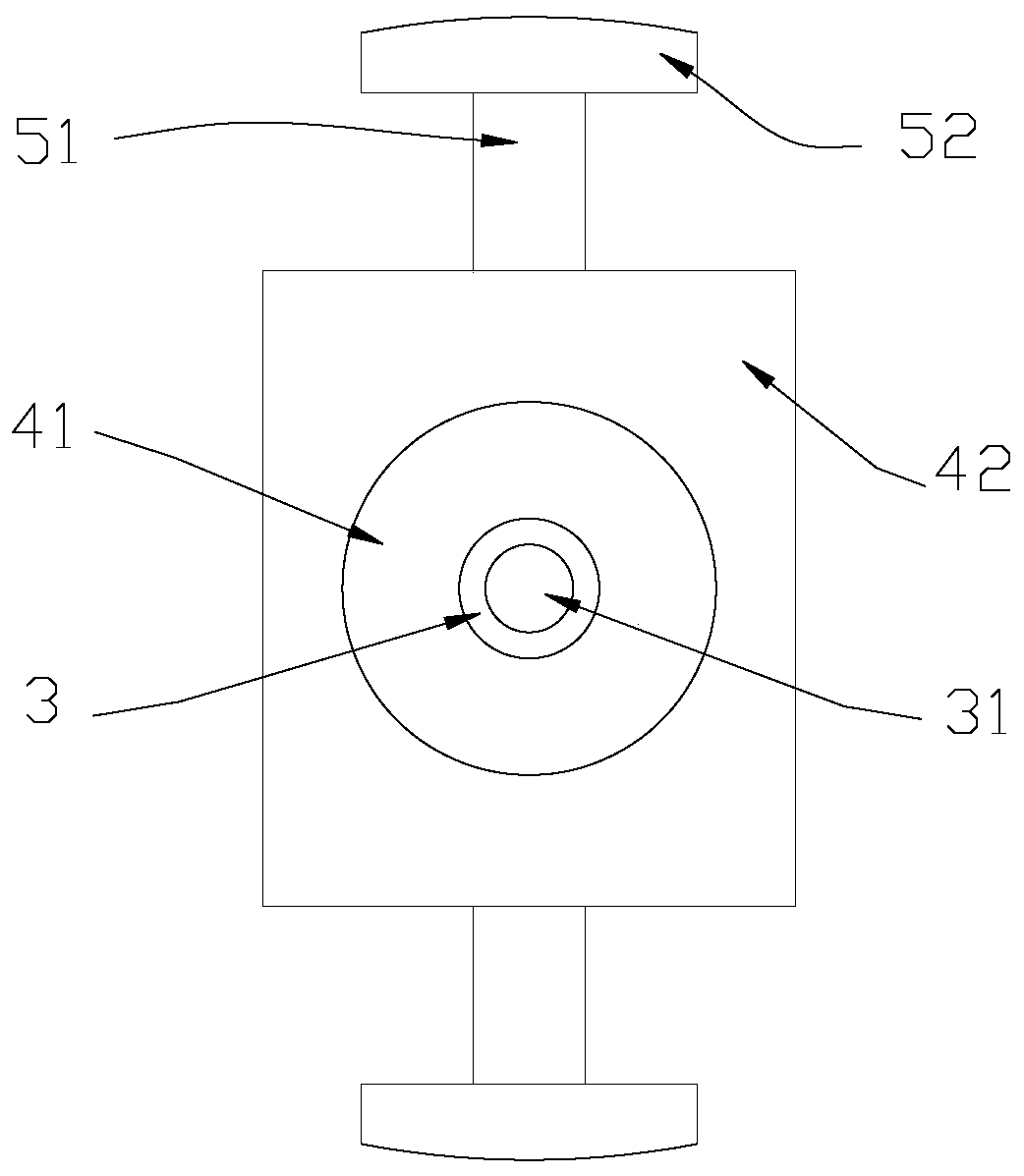
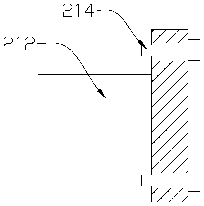
The invention discloses a steel pipe machining device based on PLC control. The steel pipe machining device comprises a supporting seat, a fixing part arranged on the supporting seat, a screw rod connected with the fixing part, two limiting parts sequentially distributed in the length direction of the screw rod, multiple supporting parts sequentially distributed in the circumferential direction ofthe screw rod, a drill bit and a power part used for driving the drill bit to drill a steel pipe. Each limiting part comprises a threaded block in threaded connection with the screw rod, and a rotating block rotationally connected with the threaded block. Each supporting part comprises two connecting parts and an ejection plate, wherein the two ends of the ejection plate are in pivot connection with the rotating blocks in the two limiting parts through the two connecting parts. The steel pipe machining device can be used for conducting drilling machining on the steel pipe effectively, the precision is high, and the effect is good.

Description

technical field [0001] The invention relates to the technical field of steel pipe processing, in particular to a steel pipe processing equipment based on PLC control. Background technique [0002] In order to facilitate the use of steel pipes, holes need to be punched on the steel pipes, but there are still some deficiencies in the existing punching machines. [0003] The patent applied for by the applicant before, application number: 201710067630.4 discloses an intelligent steel pipe drilling device, including a steel pipe fixed workbench, a drilling rig mobile workbench, an automatic feed drilling machine, a negative pressure pump and a negative pressure tank; The first guide rail is fixed on the steel pipe fixed workbench, and the steel pipe support mechanism is provided on the first guide rail, and the steel pipe support mechanism is slidably matched with the first guide rail, and the drilling rig mobile workbench is arranged on one side of the steel pipe fixed workbench...

Claims


Application Information

Patent Timeline
IPC IPC(8): B23B41/00B23Q3/06B23Q7/00
CPCB23B41/00B23Q3/064B23Q7/00
Inventor 邓小鸿王星智
Owner COLLEGE OF APPLIED SCI JIANGXI UNIV OF SCI & TECH
Learn More