Air suspension structure capable of achieving decompression type axle height passive lifting
An air suspension and axle technology, which is applied to the cantilever, suspension, elastic suspension and other directions installed on the pivot, can solve the problem of easy free fall of the axle, and achieve good safety performance, good running economy, and structural design. simple effect
- Summary
- Abstract
- Description
- Claims
- Application Information
AI Technical Summary
Problems solved by technology
Method used
Image

Examples
Embodiment 1
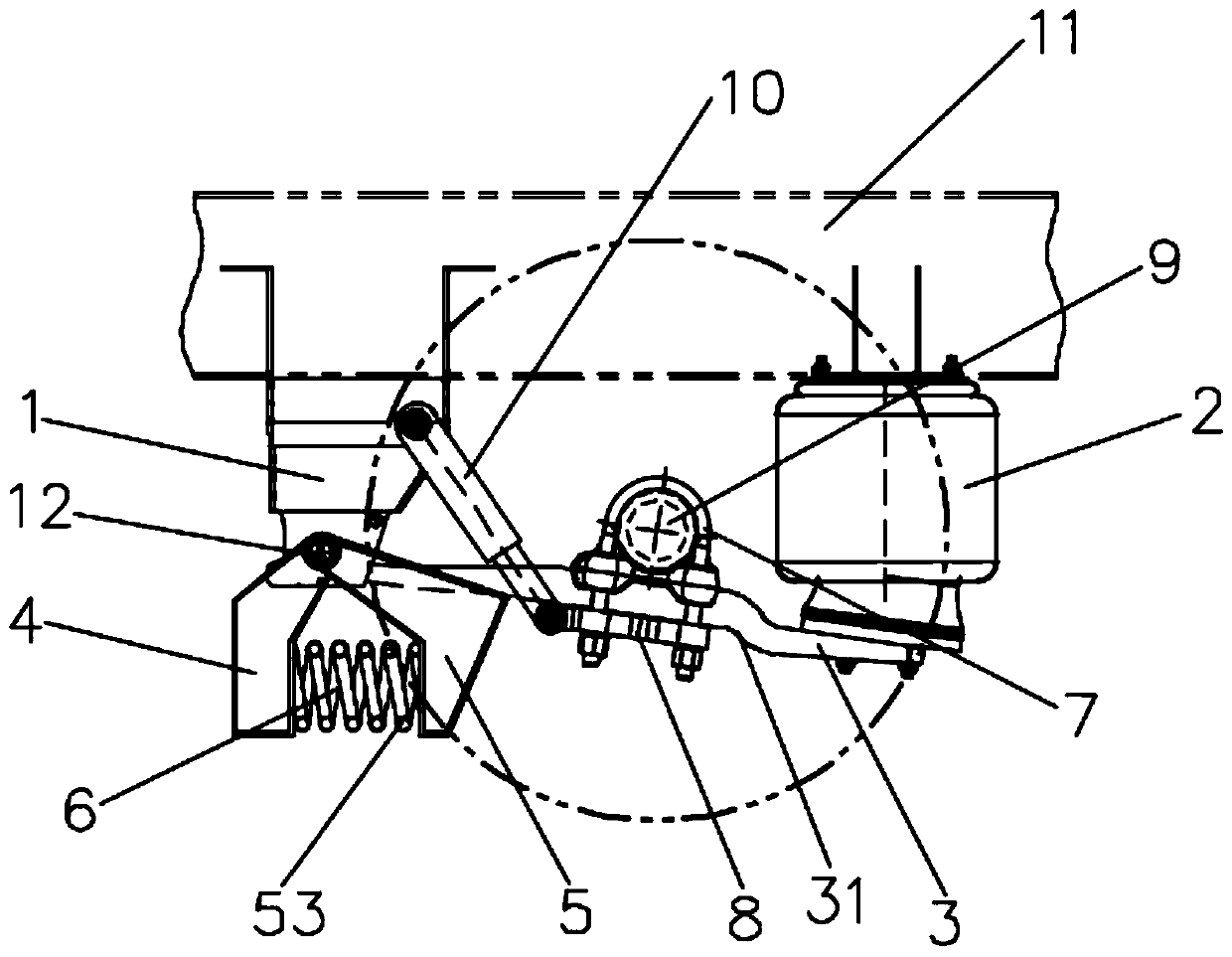
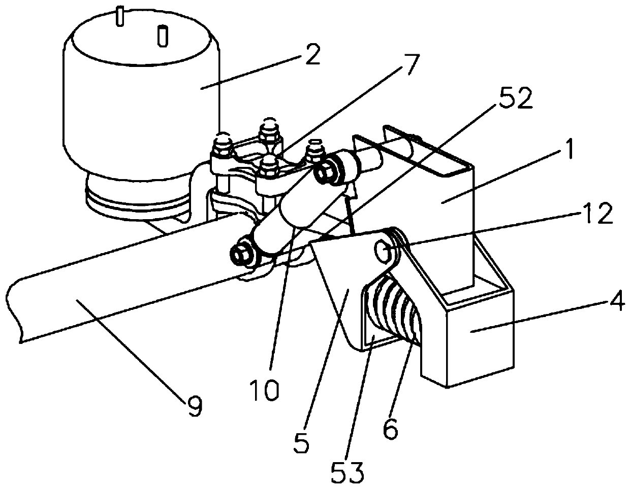
[0036] The embodiment is basically as figure 1 and figure 2 As shown: the present embodiment provides a pressure-reducing air suspension structure for passively raising the height of the wheel axle, which can be applied to vehicles such as trailers or semi-trailers that need to adjust the height of the wheel axle 9. The air suspension structure specifically includes The bracket 1 and the suspension airbag 2 on the 11, the bracket 1 is fixed and the suspension airbag 2 is respectively fixed on the vehicle frame 11 on both sides of the wheel axle 9 of the vehicle body, and the lower end of the bracket 1 is fixedly equipped with a fixed support 4. The place where it is in contact with the bracket can use an additional welding compensation plate to adjust the angle of the fixed support. Of course, other methods for adjusting the initial angle of the fixed support can also be used. The fixed support 4 can also be integrally formed with the support design; this embodiment A guide ar...
Embodiment 2
[0040] The second embodiment is basically the same as the first embodiment, the difference is that the supporting steel spring 6 provided by this embodiment is horizontally fixed on the fixed support 4, and the fixed support 4 is provided with a support for installing the supporting steel spring 6. Vertical mounting surface, so that the supporting steel spring 6 is installed stably; the elastic support mechanism provided in this embodiment also includes a steel spring push seat 5, and the steel spring push seat 5 is located below the guide arm 3 and cooperates with the lower end surface of the guide arm 3 Contact, the supporting steel spring 6 is located between the fixed support 4 and the steel spring push seat 5, the steel spring push seat 5 is connected with the end of the support steel spring 6 and supports the guide arm 3 by the steel spring push seat 5, and the steel spring push seat 5 can be fixedly connected with the supporting steel spring 6, and can also adopt a conne...
Embodiment 3
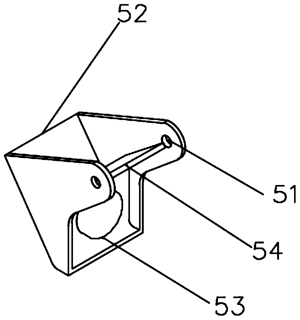
[0042] As a preferred embodiment of Embodiment 2, the present embodiment adopts a connection mode in which the steel spring push seat 5 is rotationally connected with the support 1 through the round pin 12 and is fixedly matched with the end of the supporting steel spring 6, and then the whole elastic support mechanism has better support stability; specifically, as image 3 Shown, the steel spring push seat 5 upper end is positioned at the both sides of guide arm and all is provided with connection hole, and the round pin that passes guide arm also passes the connection hole of steel spring push seat upper end both sides, to realize steel spring push seat 5 Rotately connected with the support, there is no need to additionally design the steel spring push seat 5 and the support rotating connection structure, and the inner side of the steel spring push seat is provided with a reinforcing rib 54, which simplifies the structural design and realizes the function of the steel spring ...
PUM
 Abstract
Description
Claims
Application Information
 - R&D
- Intellectual Property
- Life Sciences
- Materials
- Tech Scout
- Unparalleled Data Quality
- Higher Quality Content
- 60% Fewer Hallucinations
Browse by: Latest US Patents, China's latest patents, Technical Efficacy Thesaurus, Application Domain, Technology Topic, Popular Technical Reports.
© 2025 PatSnap. All rights reserved.Legal|Privacy policy|Modern Slavery Act Transparency Statement|Sitemap|About US| Contact US: help@patsnap.com