
Remote plasma generating device

A technology for generating device and plasma, applied to circuits, discharge tubes, electrical components, etc., can solve the problems of anode protective film damage, shedding, particle pollution, etc., and achieve the effects of easy maintenance, increased life, and reduced arc phenomenon

Inactive Publication Date: 2020-01-21
FINESSE TECH CO LTD
View PDF9 Cites 0 Cited by
  • Summary
  • Abstract
  • Description
  • Claims
  • Application Information

AI Technical Summary

Problems solved by technology

Plus, NF 3 The gas can produce etching activated particles, so it is very easy to damage or fall off the anode protective film in the cavity, causing the problem of particle pollution

Method used


Image

  • Remote plasma generating device
  • Remote plasma generating device
  • Remote plasma generating device

Examples


Embodiment Construction

[0066]In order to facilitate the understanding of the technical features, content and advantages of the present invention and the effects that can be achieved, the present invention is hereby combined with the drawings and described in detail as follows in the form of embodiments, and the purposes of the drawings used therein are only For the purpose of illustrating and assisting the description, it may not be the true proportion and precise configuration of the present invention after implementation, so the scale and configuration relationship of the attached drawings should not be interpreted to limit the scope of rights of the present invention in actual implementation. In addition, for ease of understanding, the same components in the following embodiments are described with the same symbols. Moreover, the size ratios of the components shown in the drawings are only for explaining the components and their structures, and are not intended to be limiting.

[0067] In additio...


PUM


Abstract

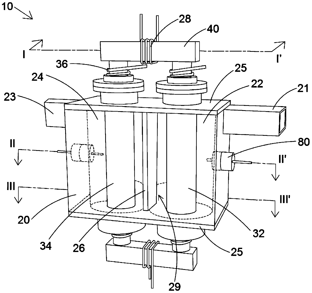
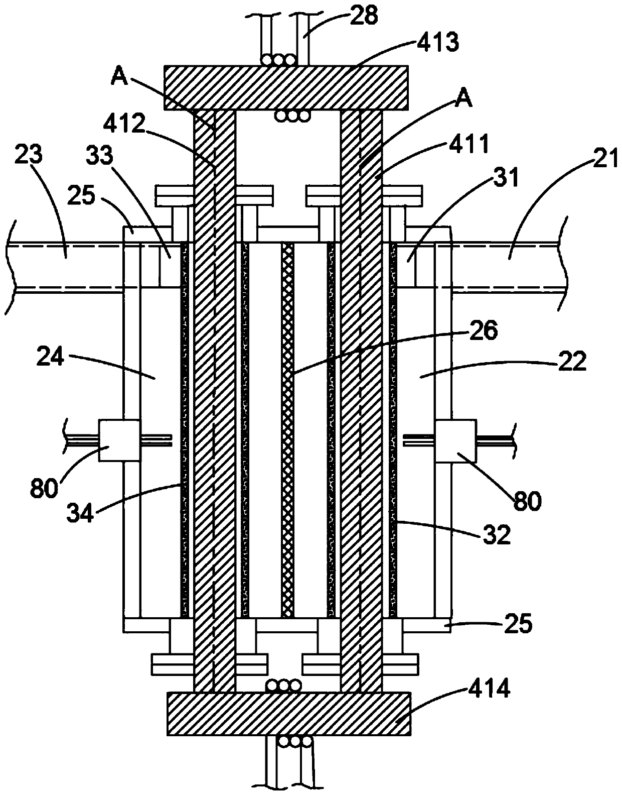
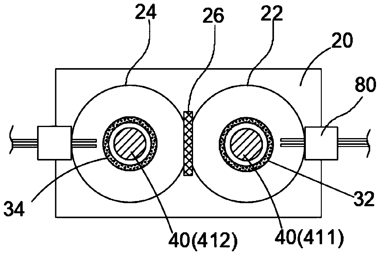
A remote plasma generating device at least comprises a reaction cavity and a magnetic core. The reaction cavity is provided with a first cavity body and a second cavity body communicated with each other and is used for introducing gas and accommodating plasma, and a dielectric assembly is arranged between the first cavity body and the second cavity body. The magnetic core penetrates through the first cavity body and the second cavity body. Gas spirally moves in the first cavity body and the second cavity body along the axis of the magnetic core. The magnetic core part in the first cavity and the magnetic core part in the second cavity generate a first axial magnetic field and a second axial magnetic field, so that a first induced angular electric field and a second induced angular electricfield are generated in the first cavity body and in the second cavity body along the axis of the magnetic core. The service life of the reaction cavity can be prolonged by reducing the impact of high-temperature gas particles on the cavity and a ceramic tube.

Description

technical field [0001] The present invention relates to a remote plasma source (Remote Plasma Source, RPS), in particular to a remote plasma generating device which can effectively reduce particle pollution. Background technique [0002] Plasma is often used in many semiconductor processes, such as the plasma-enhanced chemical vapor deposition (PECVD) process used to produce semiconductors and panels to remove process chamber residues, which has a critical impact on product yield. Although the remote plasma source (RPS) developed by MKS Instruments in the United States is the mainstream in the current market, due to the cavity design, the proper rate has been criticized. For example, US Patent No. 6,150,628 discloses a toroidal low-field reactive gas source (Toroidal Low-Field Reactive Gas Source), and its cavity design and electric field adopt a toroidal (toroidal) structure. However, its electric field will be concentrated near the dielectric shielding area (DC Break), so...

Claims


Application Information

Patent Timeline
Patent Type & Authority Applications(China)
IPC IPC(8): H01J37/32
CPCH01J37/32174H01J37/32357H01J37/3244H01J37/32669
Inventor 寇崇善
Owner FINESSE TECH CO LTD
Learn More