
Wafer driving device and method

A drying device and drying method technology, applied in the direction of electrical components, semiconductor/solid-state device manufacturing, circuits, etc., can solve the problems of peeling displacement of epitaxial wafers, destroying semiconductor structures, reducing wafer yield, quality and reliability, etc., to achieve The effect of improving the yield rate

Pending Publication Date: 2020-01-21
SHENZHEN SITAN TECH CO LTD
View PDF0 Cites 7 Cited by
  • Summary
  • Abstract
  • Description
  • Claims
  • Application Information

AI Technical Summary

Problems solved by technology

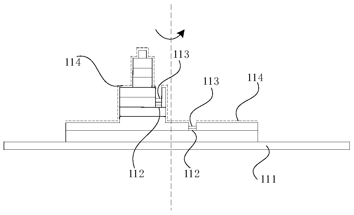
Due to the existence of uneven pits 112 in the wafer, after the cleaning process, there will usually be accumulated water in these pits, and it is difficult to dry the accumulated water 113 in the pits 112 by this method
Moreover, the semiconductor structure on the wafer is stacked by multi-layer epitaxial wafers, which generates a large centrifugal force (up to 4×10 6 Dyne), it is easy to cause greater stress to the semiconductor structure on the wafer, damage the internal structure of the semiconductor structure on the wafer, reduce the reliability and service life of the semiconductor structure on the wafer, and may directly make the epitaxial wafer The peeling displacement occurs, destroys the semiconductor structure on the wafer, and reduces the yield, quality and reliability of the wafer

Method used


Image

  • Wafer driving device and method
  • Wafer driving device and method
  • Wafer driving device and method

Examples


Embodiment 1

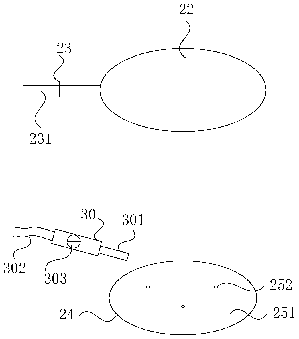
[0046] figure 2 A wafer drying device provided in Embodiment 1 of the present invention specifically includes: a shower head 22 , a vacuum chuck 24 , and a spray gun 30 .

[0047] The shower head 22 is provided with at least one spray hole for spraying cleaning liquid; specifically. The shower head 22 is connected with the liquid inlet pipe 231 to supply cleaning liquid through the liquid inlet pipe 231, wherein the cleaning liquid is isopropanol, and the wafer is cleaned with isopropanol to remove the organic matter on the wafer surface, compared to Other cleaning solutions, such as pure water, can be dried faster, thereby achieving the purpose of quickly drying the wafer. Exemplarily, at least one spray hole is arranged in a large number and evenly on the shower head 22, which can be distributed in a circle and expand layer by layer from the inside to the outside, and the spray head is a Teflon shower head. A spray switch 23 may also be provided on the liquid inlet pipe 2...

Embodiment 2

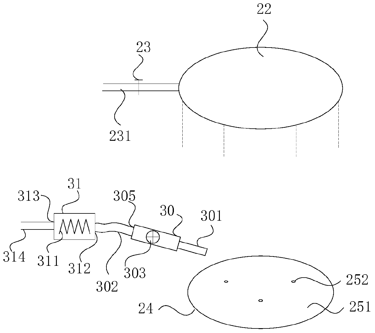
[0054] Figure 4 and Figure 5 A wafer drying device provided in Embodiment 1 of the present invention specifically includes: a liquid bucket 21, a spray head 22, a spray switch 23, a vacuum chuck 24, a vacuum pressure sensor 25, a vacuum pump 26, a vacuum valve 27, and a spray gun 30, and upper computer 28.

[0055] The liquid barrel 21 is used to hold the cleaning liquid, and the cleaning liquid is isopropyl alcohol (IPA).

[0056] The shower head 22 is provided with at least one spray hole, and the shower head 22 communicates with the liquid barrel 21 through the liquid inlet pipe 231 . Specifically, at least one spray hole is arranged in a large number and evenly on the shower head 22 , and can be distributed in a circle and expand layer by layer from the inside to the outside, and the spray head is a Teflon shower head 22 .

[0057] The spray switch 23 is arranged on the liquid inlet pipe 231, and is used to control the flow rate of the cleaning liquid. Specifically, ...

Embodiment 3

[0075] Figure 10 A wafer drying method provided in Embodiment 3 of the present invention. The wafer drying method in this embodiment can be controlled and executed by a host computer, including:

[0076] Step 202 , judging whether the wafer is fixed on the suction plate, and the suction plate includes at least one through hole.

[0077] In this embodiment, specifically, by detecting the vacuum pressure value of the through hole, and judging whether the wafer is fixed on the suction plate according to the vacuum pressure value;

[0078] In this embodiment, the vacuum pressure value of the through hole is detected by a vacuum pressure sensor disposed in the through hole of the vacuum chuck. In other embodiments, the vacuum pressure sensor can also be installed in the cavity of the vacuum chuck. Exemplarily, after the wafer is adsorbed on the carrier suction plate, the vacuum pressure sensor detects the vacuum pressure value of the through hole, and the host computer judges whe...


PUM


Abstract

The invention discloses a wafer drying device and method. The wafer drying device comprises a spray header which is provided with at least one spray hole and is used for spraying a cleaning solution;a spraying switch which is used for controlling the spraying flow of the cleaning solution; a vacuum chuck which is located below the spraying head, wherein the vacuum chuck comprises a bearing suction plate and a shell, the shell and the bearing suction plate form a cavity of the vacuum chuck, the bearing suction plate is further provided with at least one through hole penetrating through the cavity, and the bearing suction plate is used for containing the wafer; and a spray gun, wherein the spray gun port of the spray gun is arranged above the bearing suction plate, and the spray gun is usedfor spraying nitrogen to dry the wafer. According to the wafer cleaning method, the problem of drying of the wafer after cleaning is solved, and the effects of not damaging the semiconductor structure of the wafer and improving the yield, quality and reliability of the wafer in the cleaning process are achieved.

Description

technical field [0001] Embodiments of the present invention relate to a wafer drying technology, and in particular to a wafer drying device and method. Background technique [0002] A semiconductor structure on a wafer, stacked with multiple layers of epitaxial wafers. After the wafer is cleaned / etched and washed with water, it needs to be dried to remove moisture on the surface of the wafer (usually deionized pure water). In the prior art, the drying process adopts the "dynamic drying" method, see figure 1 That is, the wafer is fixed on the carrier 111, and the moisture 114 on the wafer is quickly dried by rapidly rotating the carrier 111. The rotating speed of the carrier 111 can reach 2000rpm. Due to the existence of uneven pits 112 in the wafer, after the cleaning process, there is usually accumulated water in these pits, and it is difficult to dry the accumulated water 113 in the pits 112 by this method. Moreover, the semiconductor structure on the wafer is stacked b...

Claims


Application Information

Patent Timeline
Patent Type & Authority Applications(China)
IPC IPC(8): H01L21/67H01L21/683
CPCH01L21/67051H01L21/6838
Inventor 刘召军林大野吴国才
Owner SHENZHEN SITAN TECH CO LTD
Learn More