Motor stator and its pole shoe processing method, permanent magnet motor

A technology of motor stator and processing method, which is applied in the manufacture of stator/rotor bodies, electromechanical devices, electrical components, etc., can solve problems such as improper, motor noise, poor vibration performance, and difficulty in stator quality control.

Active Publication Date: 2021-03-26
ZHUHAI GREE REFRIGERATION TECH CENT OF ENERGY SAVING & ENVIRONMENTAL PROTECTION
View PDF11 Cites 0 Cited by
  • Summary
  • Abstract
  • Description
  • Claims
  • Application Information

AI Technical Summary

Problems solved by technology

[0003] However, existing refrigeration compressors, including piston compressors, have increasingly high requirements for noise and vibration. Low noise and low vibration are the current development trend of compressors. The traditional motor stator inner diameter is equal to the circle design, and the air gap magnetic density waveform is abnormal. Sine and back EMF waveforms have high harmonic distortion rate defects, which cannot meet the existing technical requirements. Traditional motor back EMF waveforms have poor sinusoidal degree
Although the stator chute can reduce the harmonic distortion rate of the motor, the process of using the stator chute is complicated, the quality control of the stator is difficult, and the production cost is high
With the development of motor technology, the inner diameter of the stator has been adjusted from the traditional full circle arc to the form of line segment plus arc, that is, part of the arc is trimmed. This form can effectively adjust the motor pole arc coefficient and optimize the back electromotive force of the motor. However, due to the improper determination of the line segment, it will lead to an increase in the harmonic content of the back electromotive force, which will deteriorate the noise and vibration performance of the motor during operation

Method used


Image

  • Motor stator and its pole shoe processing method, permanent magnet motor
  • Motor stator and its pole shoe processing method, permanent magnet motor
  • Motor stator and its pole shoe processing method, permanent magnet motor

Examples


Embodiment Construction

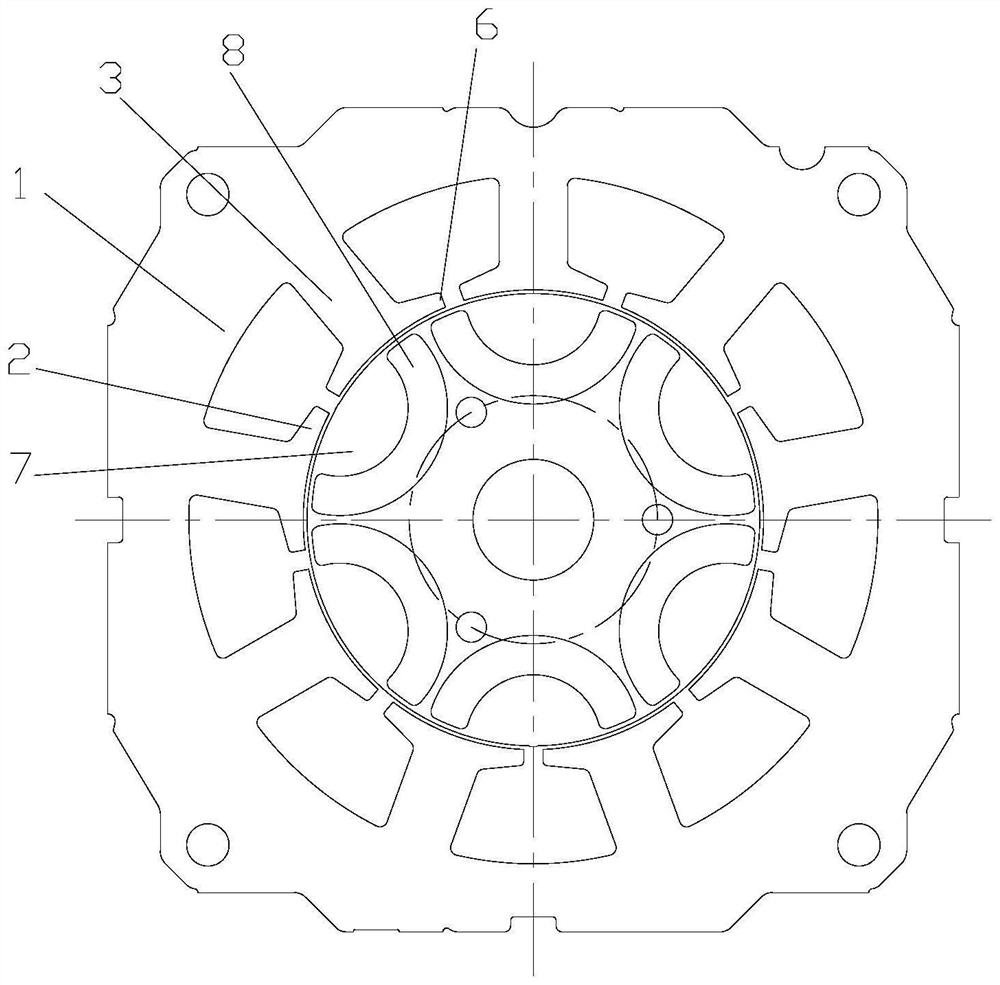
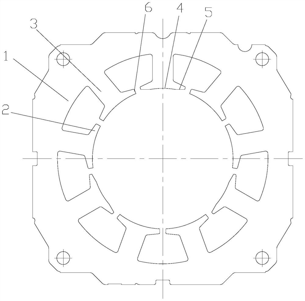
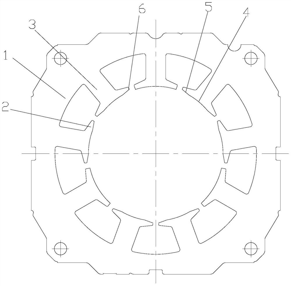
[0041] see in conjunction Figure 1 to Figure 9 As shown, according to the embodiment of the present application, the motor stator includes a yoke 1, a pole piece 2 and a stator tooth 3, and the stator tooth 3 is connected between the yoke 1 and the pole piece 2, and is perpendicular to the central axis of the yoke 1 In the cross-section, at least part of the pole shoe 2 has chamfered edges, and the radially inner peripheral wall of the chamfered pole shoe 2 includes a circular arc segment 4 extending in the circumferential direction and a straight line segment 5 located at both ends of the arc segment 4, the two straight line segments 5. It is symmetrical about the center line OH of the stator tooth 3 where the pole shoe 2 is located. The intersection point of the straight line segment 5 and the arc segment 4 is the cut pole point I, and the connection line between the cut pole point I at one end and the stator center O is OI, and OI and The angle formed by the centerline OH ...


PUM


Abstract

The invention provides a motor stator, a pole shoe processing method thereof and a permanent magnet motor. The motor stator comprises a yoke part (1), pole shoes (2) and stator teeth (3); in a cross section perpendicular to the central axis of the yoke portion (1), at least a part of the pole shoes (2) are provided with chamfered edges; the radial inner circumferential wall of the pole shoes (2) with the chamfered edge comprises an arc segment (4) and a straight line segment (5) located on the arc segment (4). An intersection point of the straight line segment (5) and the arc segment (4) is aclipping point I, the connecting line of the clipping point I at one end and the stator center O is OI, the included angle formed by OI and OH is phi, wherein theta>=phi>=theta / 2, theta = alpha-beta,alpha is the included angle between the center lines of two adjacent stator teeth (3), beta = pi / P, and P is the rotor pole number. According to the motor stator, the magnetic field distribution of the motor air gap can be improved, a back electromotive force harmonic content is greatly reduced, and the sine degree of the back electromotive force is improved.

Description

technical field [0001] The present application relates to the field of motor technology, in particular to a motor stator, a pole piece processing method thereof, and a permanent magnet motor. Background technique [0002] Permanent magnet motors are widely used in refrigeration compressors due to their simple structure and good operating performance. In the traditional motor structure design, the inner diameter and outer diameter of the stator are mostly designed to be equal circles, which is convenient for processing and dimensional inspection, and also facilitates the control of the processing size in terms of technology. [0003] However, existing refrigeration compressors, including piston compressors, have increasingly high requirements for noise and vibration. Low noise and low vibration are the current development trend of compressors. The traditional motor stator inner diameter is equal to the circle design, and the air gap magnetic density waveform is abnormal. Sin...

Claims


Application Information

Patent Timeline
Patent Type & Authority Patents(China)
IPC IPC(8): H02K1/14H02K15/02H02K29/03
CPCH02K1/14H02K15/02H02K29/03H02K2213/03
Inventor 高东东吴广荣陈华杰
Owner ZHUHAI GREE REFRIGERATION TECH CENT OF ENERGY SAVING & ENVIRONMENTAL PROTECTION
Why Eureka
Try Eureka