Valve machining assisting equipment for correcting grinding position by utilizing dielectric constant changes

A technology of dielectric constant and auxiliary equipment, applied in the field of valve processing auxiliary equipment, can solve problems such as poor chemical reaction ability, shortened service life of equipment, damage of grinding mechanism, etc., achieve high degree of automation, increase facing area, reduce positive effect on area

Active Publication Date: 2020-01-24
上饶市华益铜业有限公司
View PDF6 Cites 5 Cited by
  • Summary
  • Abstract
  • Description
  • Claims
  • Application Information

AI Technical Summary

Problems solved by technology

[0002] In the process of valve processing, the grinding of various materials is traversed. When the raw material is ground, the requirements for the ground particles are very strict. When the particles are too large, the chemical reaction ability during processing is poor and cannot be combined with other oxidation In order to ensure the quality of the valve, the grinding mechanism in the existing grinding equipment is attached to the inner wall of the grinding chamber, but the grinding mechanism will be reacted by the raw material when grinding. The grinding mechanism will tilt, or the long-term use of the equipment will cause wear to the equipment, which will also cause the grinding mechanism to shift, causing the grinding mechanism to continuously collide with the inner wall of the grinding chamber during grinding, causing damage to the inner wall of the grinding chamber and the grinding mechanism. , shorten the service life of the equipment, and if necessary, repair the equipment or replace parts, increasing the processing cost

Method used


Image

  • Valve machining assisting equipment for correcting grinding position by utilizing dielectric constant changes
  • Valve machining assisting equipment for correcting grinding position by utilizing dielectric constant changes
  • Valve machining assisting equipment for correcting grinding position by utilizing dielectric constant changes

Examples


Embodiment Construction

[0034] The following will clearly and completely describe the technical solutions in the embodiments of the present invention with reference to the accompanying drawings in the embodiments of the present invention. Obviously, the described embodiments are only some, not all, embodiments of the present invention. Based on the embodiments of the present invention, all other embodiments obtained by persons of ordinary skill in the art without making creative efforts belong to the protection scope of the present invention.

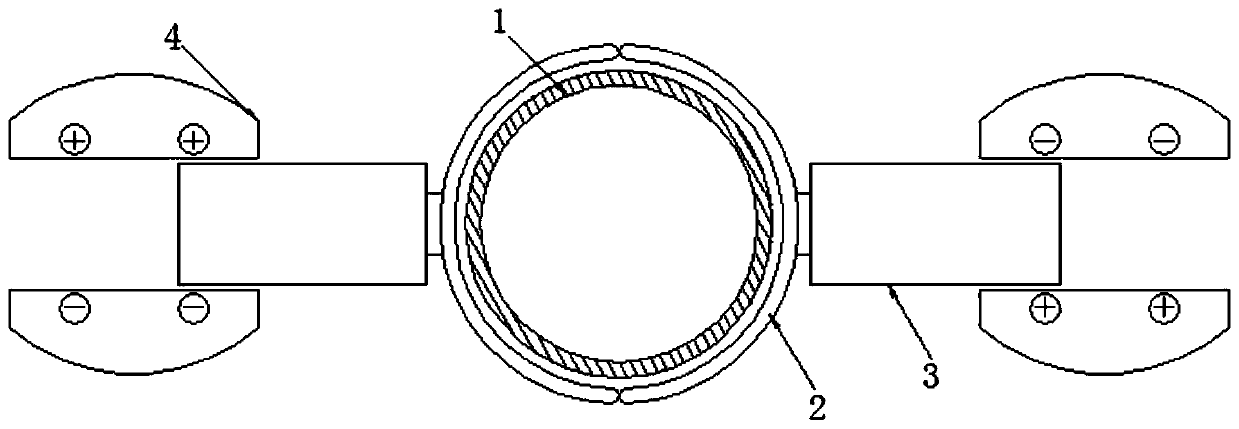
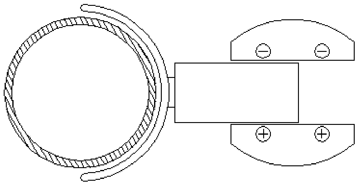
[0035] see Figure 1-17, a valve processing auxiliary equipment for correcting the grinding position by using the change of dielectric constant, comprising a grinding shaft 1, the outer side of the grinding shaft 1 is movably connected with a baffle 2, there are two baffles 2 with the same size, and the two baffles 2 are The central axis of the grinding shaft 1 is symmetrically distributed as a reference, so that the grinding shaft 1 can be in contact with the...


PUM


Abstract

The invention relates to the technical field of valve machining and discloses valve machining assisting equipment for correcting a grinding position by utilizing dielectric constant changes. The valvemachining assisting equipment comprises a grinding shaft; the outer side of the grinding shaft is movably connected with a baffle; a trigger power supply is started due to offset of the grinding shaft; a coil spring positioned at the outer side of a second rotary disc is coiled and contracted due to rotation of a first gear; subsequently the second rotary disc is used for driving a ratchet wheelto rotate; the first gear rotates to reduce the areas, facing to each other, of an dielectric plate and an electrode plate face so that the power supply is stopped and the power of the power supply isstored after being transformed into rotation circles when the power supply is connected; after the power supply is stopped, the power is released, subsequently the dielectric plate and the grinding shaft can be conveniently returned, the linkage between structures is improved, the automation degree is relatively high, and relatively high practicability is realized; a convex disc rotates to make sure that the grinding shaft returns to an initial position; the grinding shaft is automatically pushed to return to the initial position; and the offset situation which may occur subsequently is prevented.

Description

technical field [0001] The invention relates to the technical field of valve processing, in particular to a valve processing auxiliary device for correcting the grinding position by using the change of the dielectric constant. Background technique [0002] In the process of valve processing, the grinding of various materials is traversed. When the raw material is ground, the requirements for the ground particles are very strict. When the particles are too large, the chemical reaction ability during processing is poor and cannot be combined with other oxidation In order to ensure the quality of the valve, the grinding mechanism in the existing grinding equipment is attached to the inner wall of the grinding chamber, but the grinding mechanism will be reacted by the raw material when grinding. The grinding mechanism will tilt, or the long-term use of the equipment will cause wear to the equipment, which will also cause the grinding mechanism to shift, causing the grinding mech...

Claims


Application Information

Patent Timeline
Patent Type & Authority Applications(China)
IPC IPC(8): B02C23/00B02C23/04
CPCB02C23/00B02C23/04
Inventor 郑杰
Owner 上饶市华益铜业有限公司
Why Eureka
Try Eureka