Rotating electric arc welding torch with stepless eccentricity adjusting function and adjusting method thereof

A rotary arc welding, stepless adjustment technology, applied in the characteristics of electrodes, welding accessories, electrode support devices, etc., can solve the problems of severe vibration, complex assembly, inconvenient adjustment of eccentric radius, etc., to ensure stability and ensure rotation. Effect

Active Publication Date: 2020-01-24
JIANGSU UNIV OF SCI & TECH
View PDF14 Cites 0 Cited by
  • Summary
  • Abstract
  • Description
  • Claims
  • Application Information

AI Technical Summary

Problems solved by technology

[0004] The purpose of the present invention is to solve the shortcomings of the existing rotary arc welding torch, such as large volume, severe vibration, high noise, complicated assembly, inconvenient adjustment of eccentric radius, etc., and provide a rotary arc welding torch suitable for welding with stepless adjustment of eccentricity

Method used


Image

  • Rotating electric arc welding torch with stepless eccentricity adjusting function and adjusting method thereof
  • Rotating electric arc welding torch with stepless eccentricity adjusting function and adjusting method thereof
  • Rotating electric arc welding torch with stepless eccentricity adjusting function and adjusting method thereof

Examples


Embodiment Construction

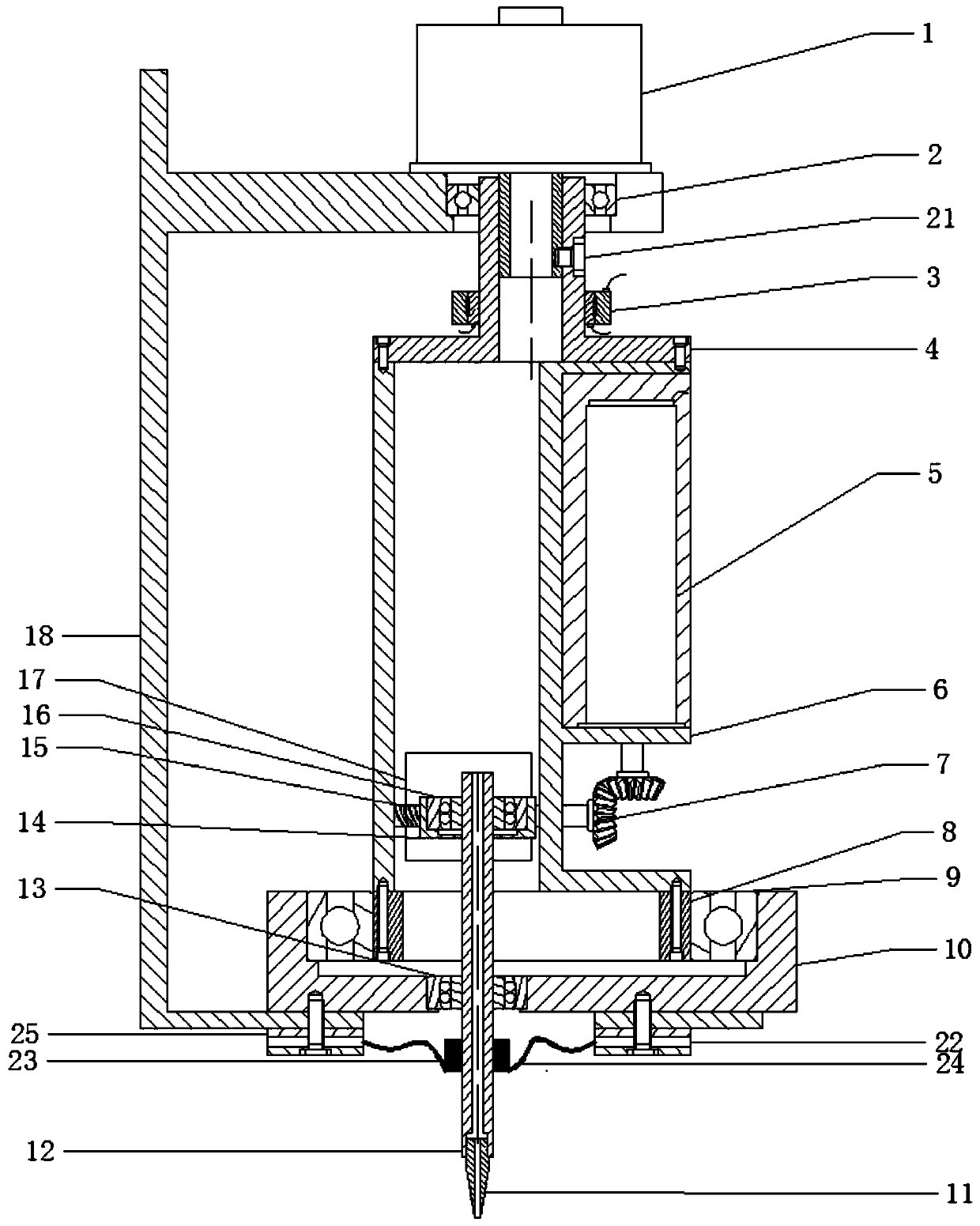
[0030] The structure and working principle of a non-polar eccentric rotating arc welding torch suitable for welding will be further described in detail below.

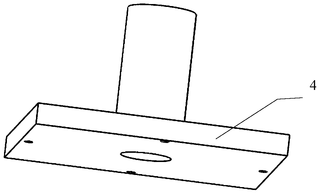
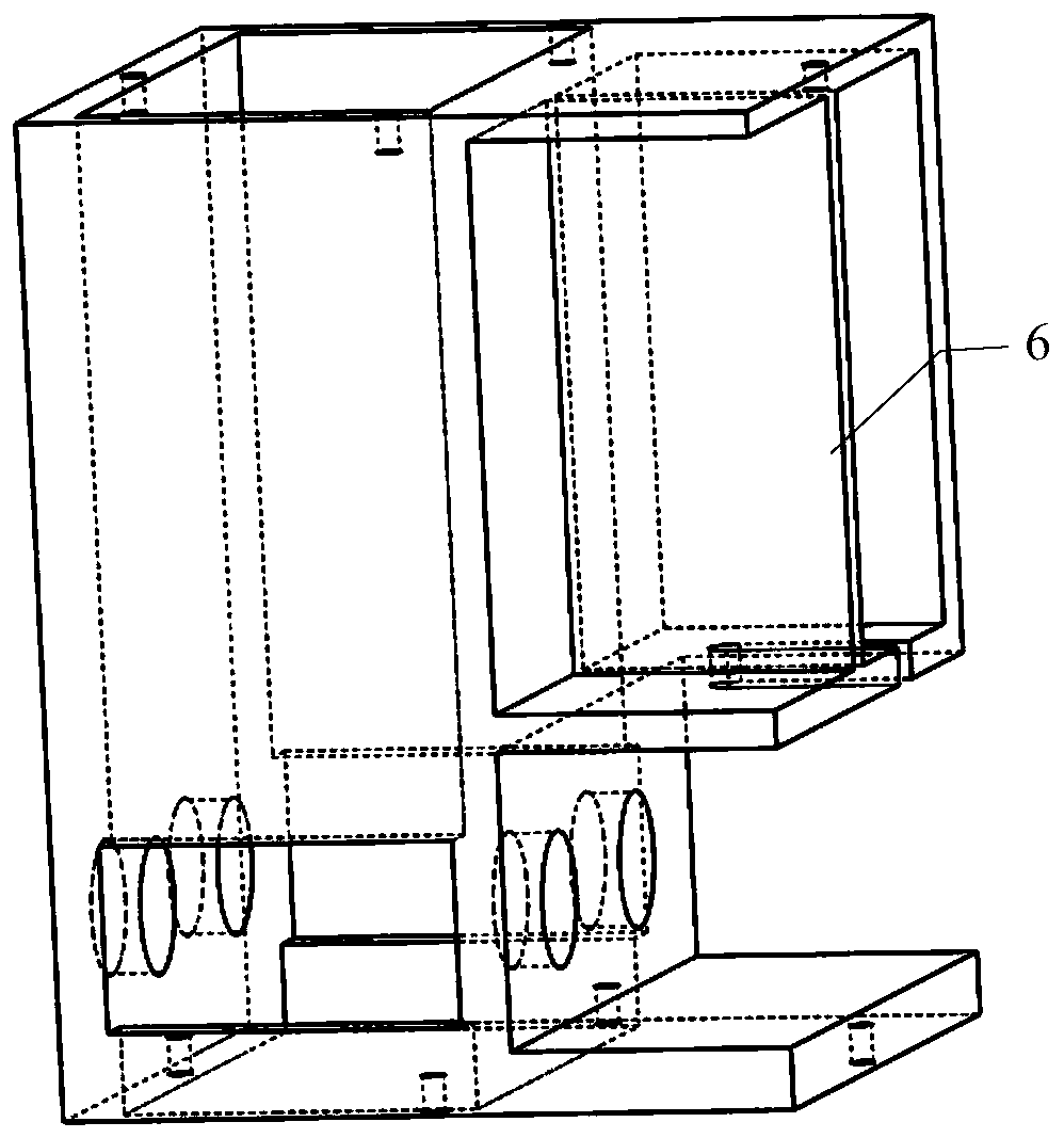
[0031] Such as figure 1 As shown, the steplessly adjustable eccentric rotating arc welding torch is composed of a frame 18, a hollow shaft motor 1, a rotating sleeve, a fixed bearing sleeve 10, and a feed system. Wherein the rotating sleeve is composed of three parts, namely an upper sleeve 4 , a middle sleeve 6 and a lower sleeve 8 . Wherein the eccentric platform is made up of the center ball bearing 16, the center ball bearing sleeve 14, the eccentric adjustment motor 5, the ball bearing 20, the bevel gear 7, the polished rod 19 and the screw mandrel 15, and the center bearing 13 is formed. The feed system includes a conductive plate 22 , a spring carbon brush 23 , a flexible cable 24 , an insulating washer 25 , a conductive rod 12 , and a conductive tip 11 .

[0032] Such as figure 1 As shown, the side of the fr...


PUM


Abstract

The invention relates to a rotating electric arc welding torch with a stepless eccentricity adjusting function and an adjusting method of the rotating electric arc welding torch. The welding torch comprises a frame. The frame is provided with a bottom plate and a top plate. The bottom plate and the top plate of the frame are respectively provided with a through hole, wherein the center lines of the through holes deviate from each other. The upper plane of the top plate is provided with a hollow shaft motor through one through hole. A fixed bearing sleeve coaxial with the hollow shaft motor isfixedly mounted on the upper plane of the bottom plate. The longitudinal section of the fixed bearing sleeve is U-shaped. A mounting hole deviating from an axial line is formed in the bottom. A lowerdeep groove ball bearing and a rotating sleeve are sequentially embedded in the fixed bearing sleeve from outside to inside. The upper end of the rotating sleeve is connected with an output shaft of the hollow shaft motor through a set screw. The middle of the rotating sleeve is provided with an eccentricity adjusting device for clamping one end of a conductive rod. The other end of the conductiverod penetrates through the mounting hole of the fixed bearing sleeve and the through hole of the bottom plate. A spring carbon brush sleeves the outer circle of the end portion. A tip is connected with a conductive nozzle. By means of the rotating electric arc welding torch with the stepless eccentricity adjusting function and the adjusting method of the rotating electric arc welding torch, stepless adjusting of the rotating radius is realized, and related noise in the operation process of the welding torch is reduced. The structure is simple, and the performance is stable.

Description

technical field [0001] The invention relates to a welding torch, more specifically to a rotary arc welding torch for stepless adjustment of eccentricity suitable for welding, and belongs to the field of welding technology. Background technique [0002] Rotary arc welding has the advantages of high production efficiency, low welding cost, and low energy consumption, and is widely used in the welding of medium and thick plates. The rotary arc is to make the welding wire or the conductive rod rotate around an axis. Nowadays, there are many researchers who study the narrow gap GMAW of the rotary arc, but there are two main ways to realize the rotary arc welding torch. One is through the conical swing of the conductive rod. , and the other is realized by means of eccentric conductive tip. The main representative institutions of conical swing are: the high-speed rotary arc welding equipment designed by Japan Steel Tube Co., Ltd. (CN87103245A), which adopts the conical swing type....

Claims


Application Information

Patent Timeline
Patent Type & Authority Applications(China)
IPC IPC(8): B23K9/28B23K9/32
CPCB23K9/28B23K9/32
Inventor 黎文航何承福王加友陈书锦黄大成
Owner JIANGSU UNIV OF SCI & TECH
Why Eureka
Try Eureka