Eureka AIR delivers breakthrough ideas for toughest innovation challenges, trusted by R&D personnel around the world.

Fully automatic PLC chip coupling device, system and method

A coupling device and fully automatic technology, applied in the coupling of optical waveguides and other directions, can solve the problems of poor repeatability and low coupling efficiency of PLC chips, and achieve the effect of easy operation, fully automatic coupling and high precision.

Inactive Publication Date: 2020-01-24
CHINA SCI PHOTON CHIP HAINING TECH CO LTD
View PDF7 Cites 4 Cited by
  • Summary
  • Abstract
  • Description
  • Claims
  • Application Information

AI Technical Summary

Problems solved by technology

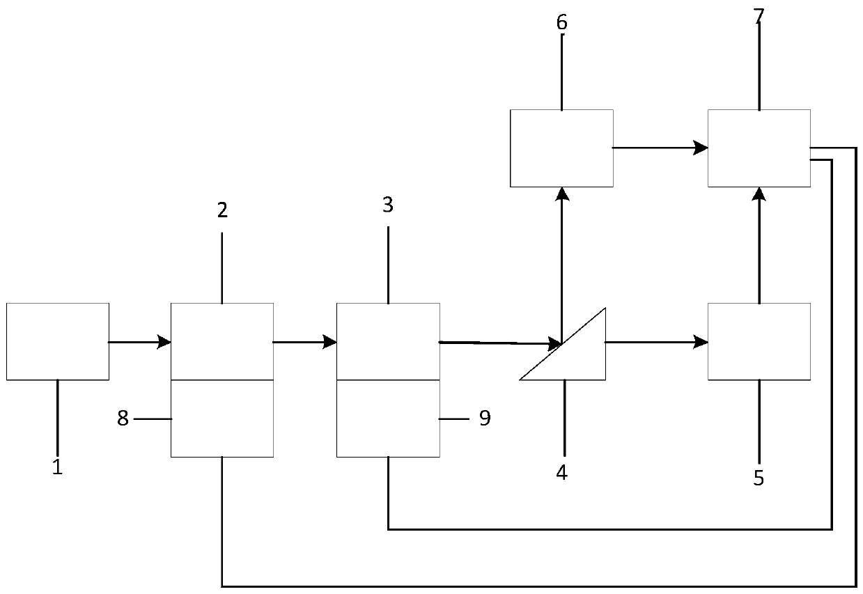
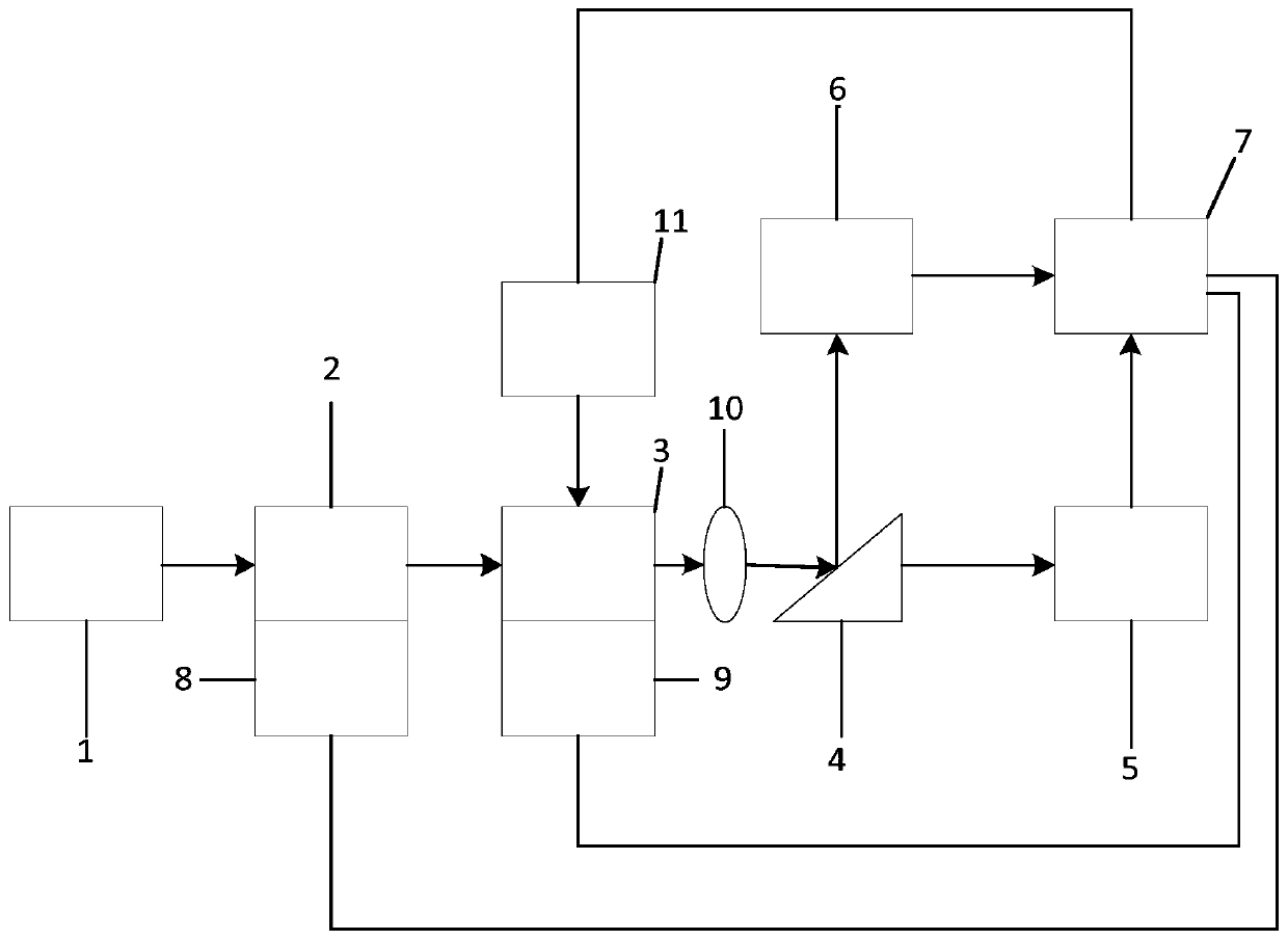
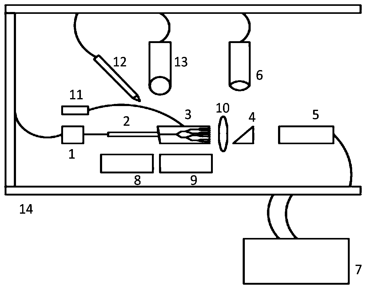
[0004] In view of this, the embodiment of the present invention provides a fully automatic PLC chip coupling device, system and method to solve the technical problems of low PLC chip coupling efficiency and poor repeatability in the prior art

Method used


Image

  • Fully automatic PLC chip coupling device, system and method
  • Fully automatic PLC chip coupling device, system and method
  • Fully automatic PLC chip coupling device, system and method

Examples


Embodiment Construction

[0031] The technical solutions of the present invention will be clearly and completely described below in conjunction with the accompanying drawings. Apparently, the described embodiments are some of the embodiments of the present invention, but not all of them. Based on the embodiments of the present invention, all other embodiments obtained by persons of ordinary skill in the art without making creative efforts belong to the protection scope of the present invention.

[0032] In the description of the present invention, it should be noted that the terms "center", "upper", "lower", "left", "right", "vertical", "horizontal", "inner", "outer" etc. The indicated orientation or positional relationship is based on the orientation or positional relationship shown in the drawings, and is only for the convenience of describing the present invention and simplifying the description, rather than indicating or implying that the referred device or element must have a specific orientation, ...


PUM


Abstract

The invention discloses a fully automatic PLC chip coupling device, system and method. The coupling device comprises a light source, a PLC chip, a beam splitter, a light power meter, a CCD, a processor, a first regulating mechanism and a second regulating mechanism, wherein the light source is used for emitting a light signal; the PLC chip receives the light signal sent by the light source throughan input light fiber and transmits the light signal to the beam splitter; the beam splitter is used for splitting the light signal into a first beam of light signal and a second beam of light signal;the CCD is used for receiving the first beam of light signal and processing the first beam of light signal to obtain a first signal, and the first signal is transmitted to the processor; the light power meter is used for receiving the second beam of light signal and processing the second beam of light signal to obtain a second signal, and the second signal is transmitted to the processor; and theprocessor is used for controlling the first regulating mechanism and / or the second regulating mechanism to move according to the first signal and the second signal. By implementing the fully automatic PLC chip coupling device, system and method, the coupling of the input light fiber and the PLC chip is jointly monitored according to the CCD and the light power meter; the coupling precision can beimproved; the operation is simple and convenient; the coupling efficiency is improved; and the coupling reliability is improved.

Description

technical field [0001] The invention relates to the technical field of optical packaging coupling, in particular to a fully automatic PLC chip coupling device, system and method. Background technique [0002] At present, all countries are vigorously promoting FTTH (Fibre (Fiber) To The Home) and FTTx (Fiber Access Network, Fiber To The x) projects. With the deepening of FTTx construction in China, the market for planar optical waveguide The demand for PLC chips has increased significantly, and planar optical waveguide PLC chips may be the focus of the next passive device market demand. As a necessary device of the system, the number of PLC chips used will continue to rise with the deployment nodes of the FTTx network. How to improve the coupling efficiency of PLC chips has become a problem that every manufacturer will consider. [0003] In the coupling process of PLC chips, most of them are coupled manually at present. However, the manual coupling method is not only ineff...

Claims


Application Information

Patent Timeline
Patent Type & Authority Applications(China)
IPC IPC(8): G02B6/26G02B6/32
CPCG02B6/26G02B6/32
Inventor 刘敬伟仝飞
Owner CHINA SCI PHOTON CHIP HAINING TECH CO LTD
Why Eureka
Eureka Blog
Learn More