Supercharge Your Innovation With Domain-Expert AI Agents!

Coil sealant encapsulating device

A sealant and potting technology, which is applied to the device and coating of the surface coating liquid, can solve the following problems such as the size cannot be too large, assembly difficulty, aging, etc., to reduce bubbles, delamination and cracks, and improve Impregnation penetration effect, effect of crack resistance and flame retardant properties

Active Publication Date: 2020-01-31
CHENGDU KAITIAN ELECTRONICS
View PDF7 Cites 1 Cited by
  • Summary
  • Abstract
  • Description
  • Claims
  • Application Information

AI Technical Summary

Problems solved by technology

The prior art potting tool has the following problems after use: The sealing of the potting tool is sealed from the side by an O-ring. Since there is no compression mechanism designed, it only relies on the O-ring groove and the O-ring on the torquer coil core. The interference between the type ring and the inner wall of the potting chamber is sealed. Due to the interference fit seal, it is difficult to assemble when the tooling and the torquer coil core are assembled together. After the potting tooling is installed, the potting and curing are completed. It also takes a lot of force to remove it when it is demoulded again, which is inconvenient to operate
.The potting tool is limited by the structure. The bottom of the potting cavity must be large and the top small, so as to form a tapered surface and facilitate demoulding. However, the size of the bottom is limited by the O-ring and cannot be too large, so the pulling out of the potting cavity The mold taper is too small, and the draft angle is only 0.4°, which also requires a large force to remove the mold after curing
After the potting glue is cured, when the potting tooling and potting cavity are removed, cracks are often generated due to the large force, and the product is not allowed to have cracks. If cracks occur, it needs to be re-potted, which is time-consuming and laborious.
.The potting tool does not consider how to carry it, so it is inconvenient to carry it every time it is put into the potting vacuum equipment
.The potting tool does not have a positioning mechanism, resulting in a large difference in the thickness of the glue on the outer layer of the torquer coil core after potting. After curing, there is intermittent turning during subsequent processing, which has a certain impact force, and it is easy to cause secondary cracking of the cured glue.
.The potting tool has no heating device, and the best flow temperature of the potting compound is 80°C±10°C. When the temperature is low, the potting compound will gradually solidify, and it will gradually age and form irreversible curing when the temperature is higher than 90°C.
Since there is no heating device, the potting glue is heated outside the vacuum equipment to 80°C and then the glue is pressed into the potting tooling in the vacuum equipment with a syringe, but due to the vacuum state, the part inside the potting glue The liquid will accelerate gasification due to low pressure, gasification absorbs a large amount of heat, and the gas formed by gasification is sucked away by the vacuum pump, resulting in a rapid drop in temperature in the vacuum equipment cavity, causing the potting compound to enter first during potting The glue and the glue that enters later solidify without being well melted together, so that the glue does not have a good inner cavity filled with the tooling in the potting, and it is easy to produce gaps, delamination or seams in the middle, resulting in air holes during curing and rift
However, gaps or cracks in the potting position are not allowed, and repotting is still required

Method used


Image

  • Coil sealant encapsulating device
  • Coil sealant encapsulating device
  • Coil sealant encapsulating device

Examples


Embodiment Construction

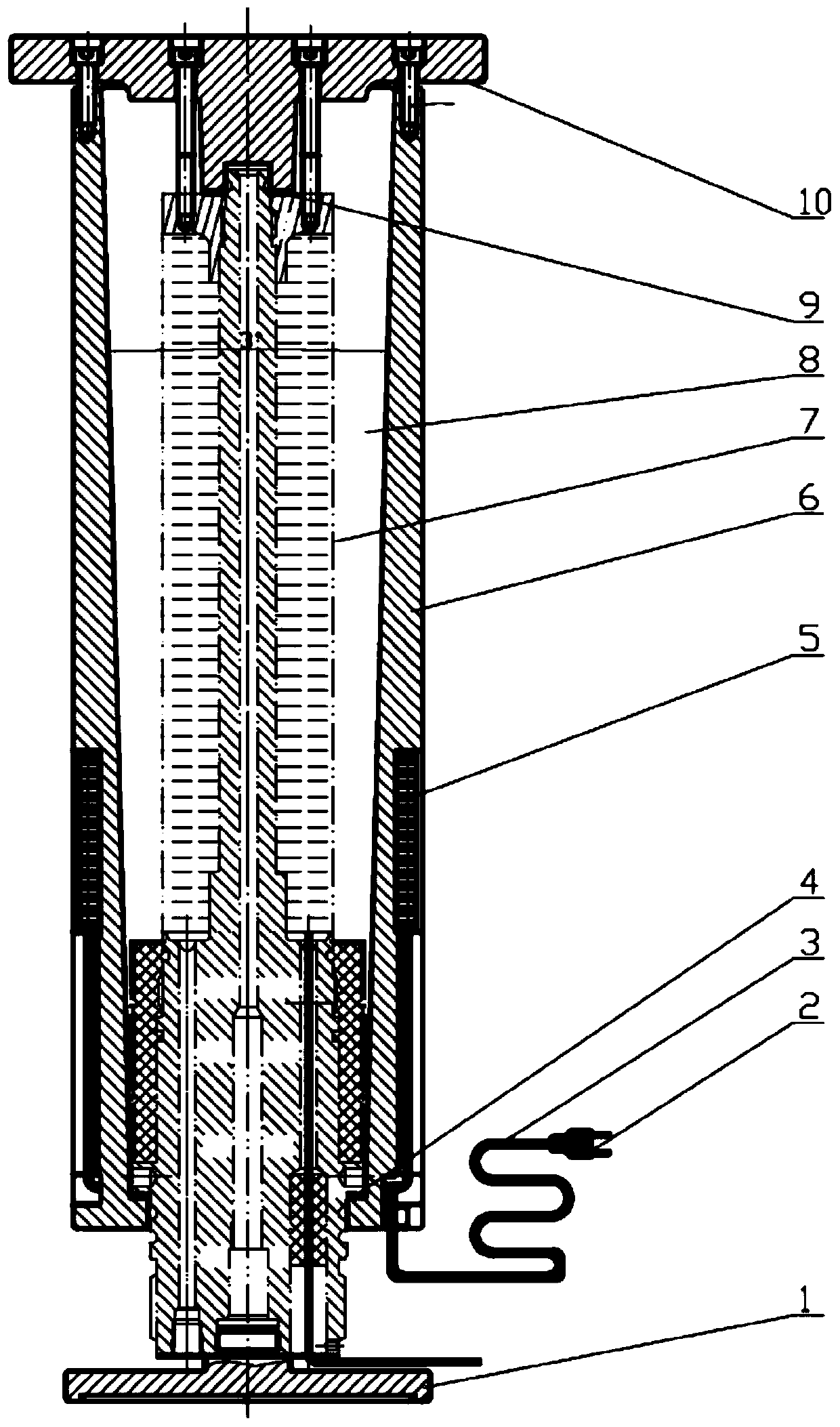
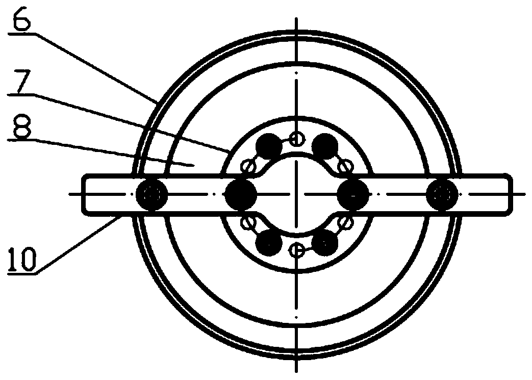
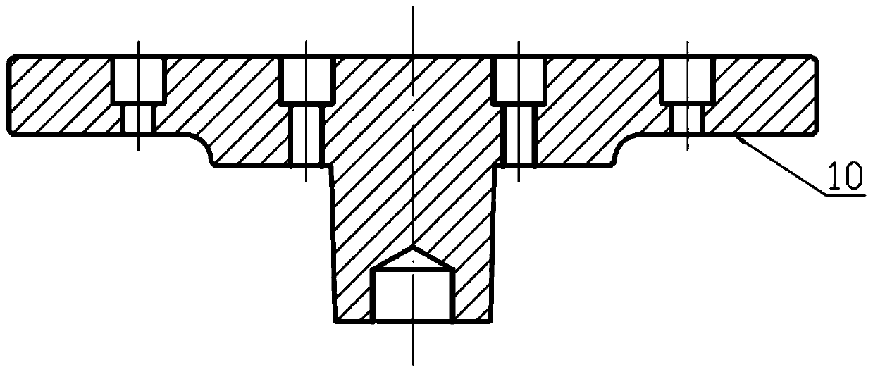
[0015] refer to Figure 1-Figure 3. In the preferred embodiment described below, a coil sealant potting device includes: the potting chamber 6 sealed by the end cap pressing plate 10 and the built-in sealing ring 9 sealed in the groove of the cylindrical boss in the center of the end cap pressing plate 10 and The load coil assembly between the base shaft shoulder rubber sealing ring 4, the inner wall of the potting chamber 6 is shaped with a conical cavity with a draft angle, the small end straight hole in the lower part of the conical cavity uses the lower end to penetrate the load coil assembly 7 and is connected with a screw thread The stepped cylindrical body of the base 1 at the lower end of the load coil assembly 7 and the sealing sleeve on its outer circle fix the load coil assembly 7 between the bottom base shoulder rubber seal ring 4 and the upper seal ring 9, and seal the chamber cylinder 6 The body is provided with a PTC heating sheet 5 surrounding the circumferent...


PUM

PropertyMeasurementUnit
Taperaaaaaaaaaa

Abstract

The invention discloses a coil sealant encapsulating device and aims to provide an encapsulating device convenient to take and free to withdrawn a pattern. The coil sealant encapsulating device is achieved by the technical scheme: a circular cone cavity of a draft angle is formed in the inner cavity of an encapsulating cavity, a straight hole in a small end on the lower part of the circular cone cavity fixes a load coil assembly between a rubber seal ring of a shaft shoulder of a base at the bottom and an upper seal ring through a stepped cylinder, the lower end of which penetrates the base ofthe load coil assembly, and a seal cover on the excircle thereof, a PTC heating sheet around a circumferential slot of an outer wall is arranged on the encapsulating cavity body, and is connected toan external power supply through a plug of a connected high-temperature wire to provide a heat source; an encapsulating sealant is injected from the top of the encapsulating cavity to the encapsulating cavity, the PTC heating sheet heats the encapsulating sealant while filling the encapsulating cavity, and the sealant is cured to form a flexible elastomer which protects the load coil assembly. Thecoil sealant encapsulating device solves the problem of gaps or cracks in an encapsulating position.

Description

technical field [0001] The invention relates to a potting device for heat conduction potting glue for potting protection of a load coil for torque measurement with high requirements on heat dissipation and temperature resistance. Background technique [0002] The thermally conductive potting compound is a two-component silicone powder plus epoxy resin to form a thermally conductive potting compound. Due to the detachability of the heat-conducting potting compound, the sealed components can be taken out for repair and replacement. It can be stored for a long time after being mixed under normal temperature conditions. It can be cured quickly under heating conditions. It has high temperature resistance and high temperature aging resistance. Good sex. After curing, it maintains rubber elasticity in a wide temperature range (-60-250°C), has excellent insulation performance, does not shrink during curing, and has better waterproof, moisture-proof and anti-aging properties. It ha...

Claims


Application Information

Patent Timeline
IPC IPC(8): B05C9/14B05C13/02
CPCB05C9/14B05C13/02
Inventor 杨国华
Owner CHENGDU KAITIAN ELECTRONICS
Features
  • R&D
  • Intellectual Property
  • Life Sciences
  • Materials
  • Tech Scout
  • Unparalleled Data Quality
  • Higher Quality Content
  • 60% Fewer Hallucinations
Learn More