
Flexible printed circuit board micro-mirror with external electromagnets for large-angle laser scanning

A printed circuit and laser scanning technology, which is applied in the field of micromirrors, can solve the problems of increased rotation angle and low strain limit, and achieve the effect of large rotation angle, reduced overall width and low cost

Inactive Publication Date: 2020-01-31
贺思源
View PDF11 Cites 3 Cited by
  • Summary
  • Abstract
  • Description
  • Claims
  • Application Information

AI Technical Summary

Problems solved by technology

[0004] However, there are two limitations for the above-mentioned FPCB magnetic micromirror, namely: 1) Since two external permanent magnets are fixed next to the FPCB structure, a large amount of extra space (width) is required outside the mirror surface, which is much larger than that outside the 4mm×4mm mirror aperture. 14.7mm (width) × 6mm (length along the axial direction); 2) Even the maximum rotation angle is higher than the second type of traditional silicon MEMS micromirror, if the FPCB beam is replaced by pure polyimide polyimide Fabricated with copper film, the rotation angle will be further increased due to the lower strain limit of copper film compared with polyimide

Method used


Image

  • Flexible printed circuit board micro-mirror with external electromagnets for large-angle laser scanning
  • Flexible printed circuit board micro-mirror with external electromagnets for large-angle laser scanning
  • Flexible printed circuit board micro-mirror with external electromagnets for large-angle laser scanning

Examples


Embodiment Construction

[0033] In order to make the purpose, technical solutions and advantages of the embodiments of the present invention clearer, the technical solutions in the embodiments of the present invention will be clearly and completely described below in conjunction with the drawings in the embodiments of the present invention. Obviously, the described embodiments It is a part of embodiments of the present invention, but not all embodiments. Based on the embodiments of the present invention, all other embodiments obtained by persons of ordinary skill in the art without making creative efforts belong to the protection scope of the present invention.

[0034] In the description of the present invention, it should be noted that the terms "center", "upper", "lower", "left", "right", "vertical", "horizontal", "inner", "outer" etc. The indicated orientation or positional relationship is based on the orientation or positional relationship shown in the drawings, and is only for the convenience of...


PUM

PropertyMeasurementUnit
Apertureaaaaaaaaaa

Abstract

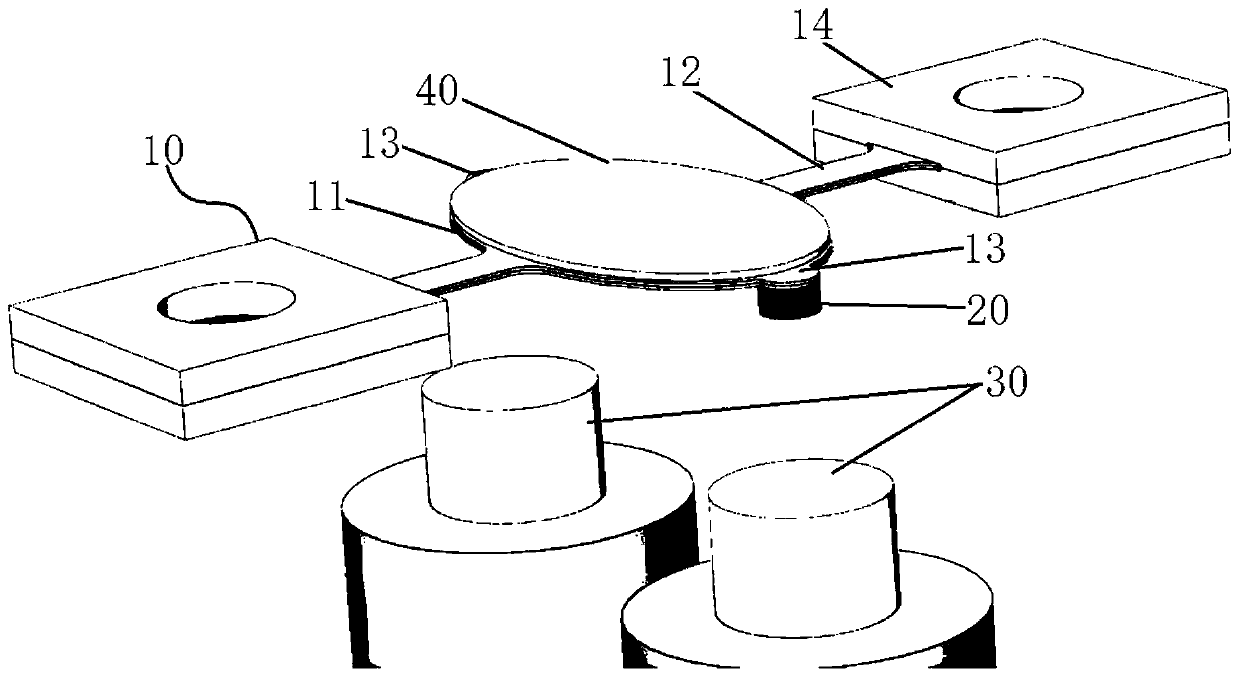
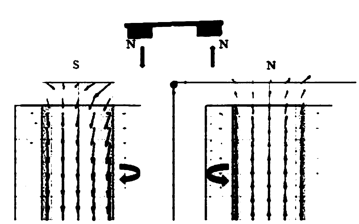
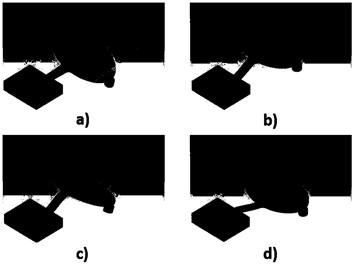
The invention discloses a flexible printed circuit board micro-mirror with external electromagnets for large-angle laser scanning. The micro-mirror comprises an FPCB structure, a mirror surface, two permanent magnet trays, and two electromagnets, wherein the FPCB structure comprises a middle seat and two torsion beams arranged on the middle seat, the mirror surface is installed above the middle seat, the two permanent magnet trays are installed below the middle seat, the two electromagnets are below corresponding permanent magnet trays, one electromagnet and one permanent magnet tray attract each other, the other electromagnet and the other permanent magnet tray reject each other, so that the attraction and repulsion help rotate the mirror surface. Two mobile permanent magnet trays and twoexternal electromagnets are arranged below the FPCB structure, so that extra permanent magnets are not needed beside the FPCB structure, and the overall width outside the mirror surface can be reduced. The FPCB structure has no mobile coil, producing no Lorentz force, therefore, the torsion beam can be made of pure polyimide, so as to obtain a larger maximum rotation angle.

Description

technical field [0001] The invention relates to the technical field of micromirrors, in particular to an external electromagnet flexible printed circuit board micromirror for large-angle laser scanning. Background technique [0002] Due to small size, high integration, high reliability and low cost, MEMS micromirrors have been widely and successfully applied in displays, optical switches and medical devices. Laser scanners are one of the main applications of micromirrors, namely barcode reading, light detection and ranging (lidar), structured light depth sensing and biological imaging, etc. [0003] MEMS micromirrors can be divided into two types according to the fabrication method and aperture size of the mirror surface. The first type is the mirror and the actuator as a whole, the aperture is usually less than 1mm and the radius of curvature of the flatness is usually less than 1m. The second type is to achieve a large aperture (several millimeters) under high flatness (...

Claims


Application Information

Patent Timeline
IPC IPC(8): G02B26/10
CPCG02B26/105
Inventor 贺思源
Owner 贺思源
Learn More