
Compensation device for empty load and temperature rising test system of +/-800kV power transmission and transformation main equipment

A compensation device and temperature rise test technology, applied in circuit devices, reactive power compensation, measurement devices, etc., can solve the problems of single compensation combination, large power supply capacity requirements, and poor system reliability, achieving a wide range of applications and saving construction The effect of large cost and total capacity

Active Publication Date: 2020-01-31
ELECTRIC POWER RESEARCH INSTITUTE OF STATE GRID QINGHAI ELECTRIC POWER COMPANY +3
View PDF15 Cites 0 Cited by
  • Summary
  • Abstract
  • Description
  • Claims
  • Application Information

AI Technical Summary

Problems solved by technology

At present, the technology mostly adopts the fixed compensation method. In actual use, there will be a large number of undercompensation or overcompensation phenomena. The application range is small and it is inconvenient to use.
The severe discharge phenomenon in the high-voltage environment affects the quality of the power supply. At the same time, the compensation device uses a solenoid valve for capacitor switching, which leads to out-of-control phenomena and poor system reliability.
[0003] In summary, the existing compensation devices have the following problems: 1. The operation is complex and requires the coordination and cooperation of multiple people, and the efficiency is low; 2. The compensation combination method is single, and the compensation error is relatively large The requirements for power supply capacity are still large, and the scope of application is small; 3. The severe discharge phenomenon in the compensation device increases the burden on the power supply and the quality of the compensated power supply is poor; 4. Relays or solenoid valves are often used for switching, and under the influence of high voltage, it will appear out of control. , poor system reliability

Method used


Image

  • Compensation device for empty load and temperature rising test system of +/-800kV power transmission and transformation main equipment
  • Compensation device for empty load and temperature rising test system of +/-800kV power transmission and transformation main equipment
  • Compensation device for empty load and temperature rising test system of +/-800kV power transmission and transformation main equipment

Examples


Embodiment 1

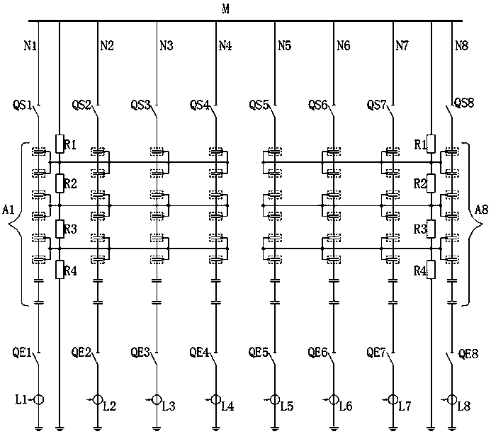
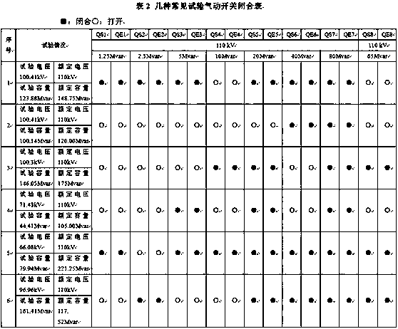
[0021] Embodiment 1, the present invention provides a compensation device for the no-load and temperature rise test system of ±800kV power transmission and transformation main equipment. The bus M is connected to 8 branches N1-N8 in parallel, and the branches include a capacitor bank A1 composed of capacitors connected in series. -A8, and the pneumatic isolating switches QS1-QS8 set between the capacitor bank and the busbar and the pneumatic isolating switches QE1-QE8 set between the capacitor bank and the ground, the lower end of the branch circuit is connected to the current transformer for the test, the branch circuit The bottom end is grounded.

[0022] The whole set of compensation device is divided into two capacitor towers, each tower has 4 branches, and each capacitor tower is equipped with a set of clamping resistors composed of 4 resistors, the bottom end of the clamping resistors is grounded, and the clamping resistors are connected in series Connect the capacitor c...


PUM


Abstract

The invention provides a compensation device for an empty load and temperature rising test system of + / -800kV power transmission and transformation main equipment and relates to the technical field ofelectrical test equipment. The compensation device is characterized in that a bus is connected with eight branch circuits connected in parallel, wherein each branch circuit comprises a capacitor bankformed by connecting capacitors in series, a pneumatic isolating switch arranged between the capacitor bank and the bus and a pneumatic isolating switch arranged between the capacitor bank and the ground, a lower end of each branch circuit is connected with a current transformer or a voltage transformer for testing, and the lowest end of each branch circuit is grounded. The compensation device isadvantaged in that the total compensation capacity is large, compensation stage difference is small, the number of compensation combinations is large, most of current converter transformers can be tested, and the application range is wide; local and remote control can be realized, field operation is facilitated, working efficiency is improved, and test safety and reliability are improved; a high-voltage discharge phenomenon is effectively improved, and the power supply quality and stability of the whole test system are improved.

Description

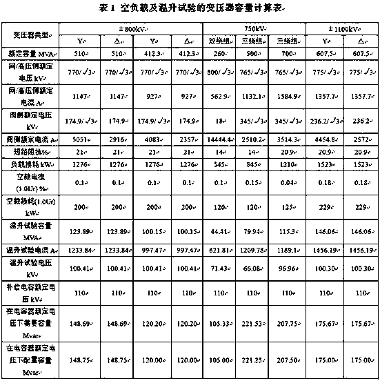
technical field [0001] The invention relates to the technical field of electrical test equipment, in particular to a compensation device for an empty load and temperature rise test system of ±800kV power transmission and transformation main equipment. Background technique [0002] When doing the converter transformer empty load and temperature rise test of the main equipment of ±800kV power transmission and transformation, the capacity of the power supply is required to be relatively large. The laboratory does not have a power supply that meets the requirements, and the main loss of this experiment is inductive reactive power, which does not meet the requirements of the power grid. Efficiency requirements, in order to reduce the power supply capacity of the laboratory and improve efficiency, it is necessary to use a capacitive reactive power compensation device when doing such tests. At present, the technology mostly adopts the fixed compensation method. In actual use, there...

Claims


Application Information

Patent Timeline
IPC IPC(8): H02J3/18H02J13/00G01R31/00
CPCH02J3/1864G01R31/00Y04S10/22Y02E40/30Y02E40/70
Inventor 王理丽王生杰于鑫龙王生富沈洁林万德杨放南马旭东包正红张成磊蒋玲李占林李渊刘有平
Owner ELECTRIC POWER RESEARCH INSTITUTE OF STATE GRID QINGHAI ELECTRIC POWER COMPANY
Learn More