Guide rail punch forming device

A stamping forming and guide rail technology, which is applied in the direction of feeding device, positioning device, storage device, etc., can solve the problem that the guide rail cannot be automatically loaded and discharged

Active Publication Date: 2020-02-04
平湖市晨丰五金有限公司
View PDF8 Cites 15 Cited by
  • Summary
  • Abstract
  • Description
  • Claims
  • Application Information

AI Technical Summary

Problems solved by technology

[0004] The purpose of the present invention is to provide a guide rail stamping and forming device, which solves the probl

Method used

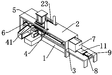
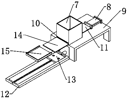
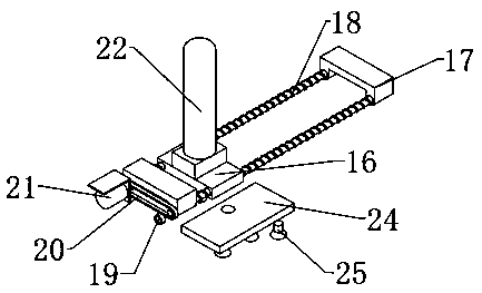

Image

  • Guide rail punch forming device
  • Guide rail punch forming device
  • Guide rail punch forming device

Examples


Embodiment Construction

[0024] The technical solutions of the present invention will be further described below in conjunction with the accompanying drawings and through specific implementation methods.

[0025] Wherein, the accompanying drawings are only for illustrative purposes, showing only schematic diagrams, rather than physical drawings, and should not be construed as limitations on this patent; in order to better illustrate the embodiments of the present invention, some parts of the accompanying drawings will be omitted, Enlargement or reduction does not represent the size of the actual product; for those skilled in the art, it is understandable that certain known structures and their descriptions in the drawings may be omitted.

[0026] In the drawings of the embodiments of the present invention, the same or similar symbols correspond to the same or similar components; , "inner", "outer" and other indicated orientations or positional relationships are based on the orientations or positional ...


PUM


Abstract

The invention relates to the field of guide rail production, in particular to a guide rail punch forming device. The device comprises a workbench and further comprises a support, a feeding assembly, aloading assembly, a punching assembly and a discharging assembly. The feeding assembly is arranged on the workbench. The loading assembly is arranged on the support and located on one side of the upper portion of the feeding assembly. The punching assembly is arranged at one end of the feeding assembly. The discharging assembly is arranged at the end, away from the feeding assembly, of the punching assembly. The feeding assembly comprises a pushing mechanism and a delivering mechanism. The pushing mechanism is arranged at one end of the workbench. The delivering mechanism is arranged on the workbench and located between the pushing mechanism and the punching assembly. The pushing mechanism, the delivering mechanism, the punching assembly and the discharging assembly are arranged linearlyin the length direction of the workbench in sequence. By means of the guide rail punch forming device, the problem that automatic loading and discharging fail to be performed during guide rail punch forming is solved, the human cost is lowered, and the production efficiency is improved.

Description

technical field [0001] The invention relates to the field of guide rail production, in particular to a guide rail punching and forming device. Background technique [0002] Mold is a kind of production equipment widely used in industrial production. Molds are divided into plastic molds, stamping molds, injection molds, etc. Among them, the stamping die is a special process equipment for processing materials into parts in cold stamping processing, called a cold stamping die. Stamping is at room temperature, using a mold installed on a press machine to apply pressure to the material, making the material A processing method that produces separation or plastic deformation to obtain parts of a certain shape and size. [0003] Stamping technology has a wide range of applications. In all sectors of the national economy, there are almost all stamping products. With the increase of market requirements for product cost and cycle, it has become a technical and It is an important dire...

Claims


Application Information

Patent Timeline
IPC IPC(8): B21D22/02B21D43/00B21D43/20B21D43/18B21D45/04B21C51/00B30B15/32
CPCB21C51/00B21D22/02B21D43/003B21D43/18B21D43/20B21D45/04B30B15/32
Inventor 周小鹏
Owner 平湖市晨丰五金有限公司
Why Eureka
Try Eureka