Strong-combined composite material plate

A composite material board and composite material technology, applied in the field of composite material boards, can solve the problems of high process cost, weak impact resistance, large environmental pollution, etc., and achieve the effect of simple connection process, reasonable structure design and high bonding strength

Pending Publication Date: 2020-02-04
合肥山秀碳纤科技有限公司
View PDF0 Cites 1 Cited by
  • Summary
  • Abstract
  • Description
  • Claims
  • Application Information

AI Technical Summary

Problems solved by technology

[0003] For example, in the prior art, such as a computer casing, the use of a plastic casing has disadvantages such as low strength and weak impact resistance. For example, a composite material casing such as carbon fiber is used, which is not only light in weight, but also high in strength and strong in impact resistance. Existing composite materials The splicing with the plastic shell is generally bonded by spraying glue, which has poor adhesion and weak bonding. In addition, spraying glue has a large environmental pollution, which has adverse effects on the operator's body, and requires many operating procedures. Production higher cost
[0004] Other existing buckle connection methods require high pressure to extrude the sandwich layer in the composite material board or high pressure to extrude plastic into the sandwich layer for connection. This connection method has high process costs.

Method used


Image

  • Strong-combined composite material plate
  • Strong-combined composite material plate
  • Strong-combined composite material plate

Examples


Embodiment 1

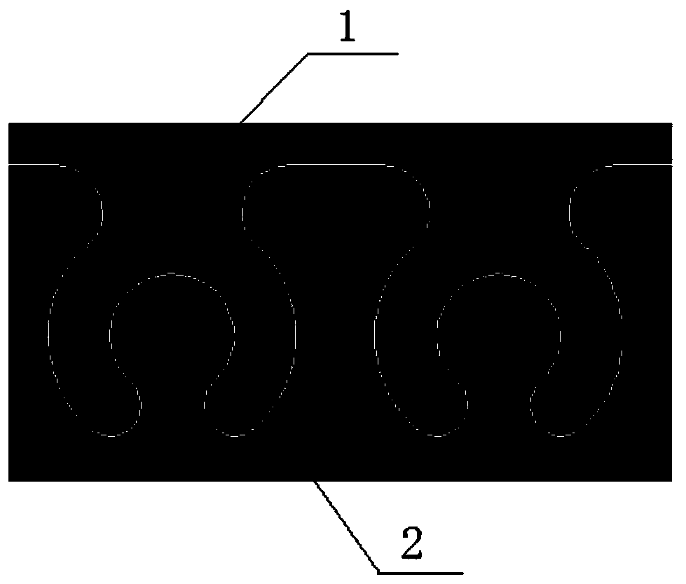
[0029] Such as figure 1 with image 3 As shown, a composite material plate with strong combination includes a composite material plate 1, a thermoplastic material frame 2 connected to the outer periphery of the composite material plate 1 by injection molding; the end surface of the composite material plate 1 is cut with concave and convex surfaces, and the thermoplastic material The concave-convex surface of the filling end surface is combined with the composite material plate 1;

[0030] The composite material plate 1 is provided with a sawtooth groove 3, and the composite material plate 1 and the thermoplastic material frame 2 are connected to each other through the sawtooth groove 3; the shapes of the two adjacent sawtooth grooves on the composite material plate 1 are the same; The inside of the sawtooth groove 3 is provided with a groove whose opening size is larger than the opening of the sawtooth groove;

[0031] The composite material board 1 includes a solid board an...

Embodiment 2

[0036] Such as figure 1 , Figure 4 with Figure 5 As shown, a composite material plate with strong combination includes a composite material plate 1, a thermoplastic material frame 2 connected to the outer periphery of the composite material plate 1 by injection molding; the end surface of the composite material plate 1 is cut with concave and convex surfaces, and the thermoplastic material The concave-convex surface of the filling end surface is combined with the composite material plate 1;

[0037] The composite material plate 1 is provided with a sawtooth groove 3, and the composite material plate 1 and the thermoplastic material frame 2 are connected to each other through the sawtooth groove 3; the shapes of the two adjacent sawtooth grooves on the composite material plate 1 are different; The inside of the sawtooth groove 3 is provided with a groove whose opening size is larger than the opening of the sawtooth groove;

[0038] The composite material board 1 includes a...

Embodiment 3

[0042] Such as figure 2 with Image 6 As shown in the figure, a solidly combined composite material plate includes a composite material plate 1, and a thermoplastic material frame 2 connected to the outer periphery of the composite material plate 1 by injection molding;

[0043] The composite material plate 1 is provided with a sawtooth groove 3, and the composite material plate 1 and the thermoplastic material frame 2 are connected to each other through the sawtooth groove 3; the shapes of the adjacent two sawtooth grooves 3 on the composite material plate 1 are the same ; The inside of the sawtooth groove 3 is provided with two grooves whose opening size is larger than the opening of the sawtooth groove 3;

[0044] The composite material board 1 includes a solid board and a sandwich board; wherein the sandwich board includes a solid sandwich and a foamed structure sandwich. The solid sandwich core and the foam structure sandwich core are provided with skins made of fiber ...


PUM


Abstract

The invention discloses a strong-combined composite material plate. The strong-combined composite material plate comprises a composite material plate (1) and a thermoplastic material frame (2) connected to the periphery of the composite material plate (1) in an injection molding mode; the end surface of the composite material plate (1) is cut to form a concave-convex surface, and the concave-convex surface of the end surface is filled with a thermoplastic material and then is combined with the composite material plate (1); the composite material plate (1) or the thermoplastic material frame (2) is provided with sawtooth grooves, and the composite material plate (1) and the thermoplastic material frame (2) are connected in a meshed mode through the sawtooth grooves; the shapes of two adjacent sawtooth grooves in the composite material plate (1) or the thermoplastic material frame (2) are the same or different; and one or more grooves with the opening size larger than that of the openings of the sawtooth grooves are formed in the sawtooth groove. The strong-combined composite material plate has a reasonable structural design, and has the advantages of high bonding strength, firm structure, simple connecting process and good environmental protection property due to the fact that the one or more sawtooth-shaped grooves are adopted for meshed connection.

Description

technical field [0001] The invention relates to a fiber material panel, in particular to a firmly bonded composite material plate. Background technique [0002] With the rapid development of my country's economy, various household appliances, electronic products, motor vehicles and aerospace equipment have been developed rapidly. The shells of these products generally require strong hardness, strong impact resistance, heat resistance and corrosion resistance. [0003] For example, in the prior art, such as a computer casing, the use of a plastic casing has disadvantages such as low strength and weak impact resistance. For example, a composite material casing such as carbon fiber is used, which is not only light in weight, but also high in strength and strong in impact resistance. Existing composite materials Splicing glue with the plastic shell is generally bonded by spraying glue, which has poor bonding force and weak bond. In addition, spraying glue has great environmental...

Claims


Application Information

Patent Timeline
Patent Type & Authority Applications(China)
IPC IPC(8): B32B3/06B32B27/06B32B27/38B32B5/18B32B9/00B32B9/04B32B17/02B32B17/06B32B17/04B32B27/02B32B27/34B32B27/04H05K5/00
CPCB32B3/06B32B5/02B32B5/08B32B5/18B32B27/06B32B27/38B32B2260/021B32B2262/0269B32B2262/10B32B2262/101B32B2262/106B32B2262/14H05K5/00
Inventor 张春笋
Owner 合肥山秀碳纤科技有限公司
Why Eureka
Try Eureka