Axial oil collecting ring and inner-ring lubricating device and method of aviation engine main bearing

An oil collection ring and axial technology, which is applied in the direction of engine lubrication, engine components, engine cooling, etc., can solve the problems of simple jet lubrication structure, achieve high oil collection efficiency, meet the needs of lubrication and cooling, and reduce spatter Effect

Active Publication Date: 2020-02-04
西安瑞谱捷特动力技术有限公司
View PDF6 Cites 7 Cited by
  • Summary
  • Abstract
  • Description
  • Claims
  • Application Information

AI Technical Summary

Problems solved by technology

The traditional spray lubrication has a simple structure and is only suitable for bearings with low speed and less heat input from the main shaft; high-performance aeroengines adopt the oil supply lubrication method under the ring with high lubrication efficiency, which can provide high speed and heat transfer to the main shaft More bearings provide sufficient lubricant

Method used


Image

  • Axial oil collecting ring and inner-ring lubricating device and method of aviation engine main bearing
  • Axial oil collecting ring and inner-ring lubricating device and method of aviation engine main bearing
  • Axial oil collecting ring and inner-ring lubricating device and method of aviation engine main bearing

Examples


Embodiment 1

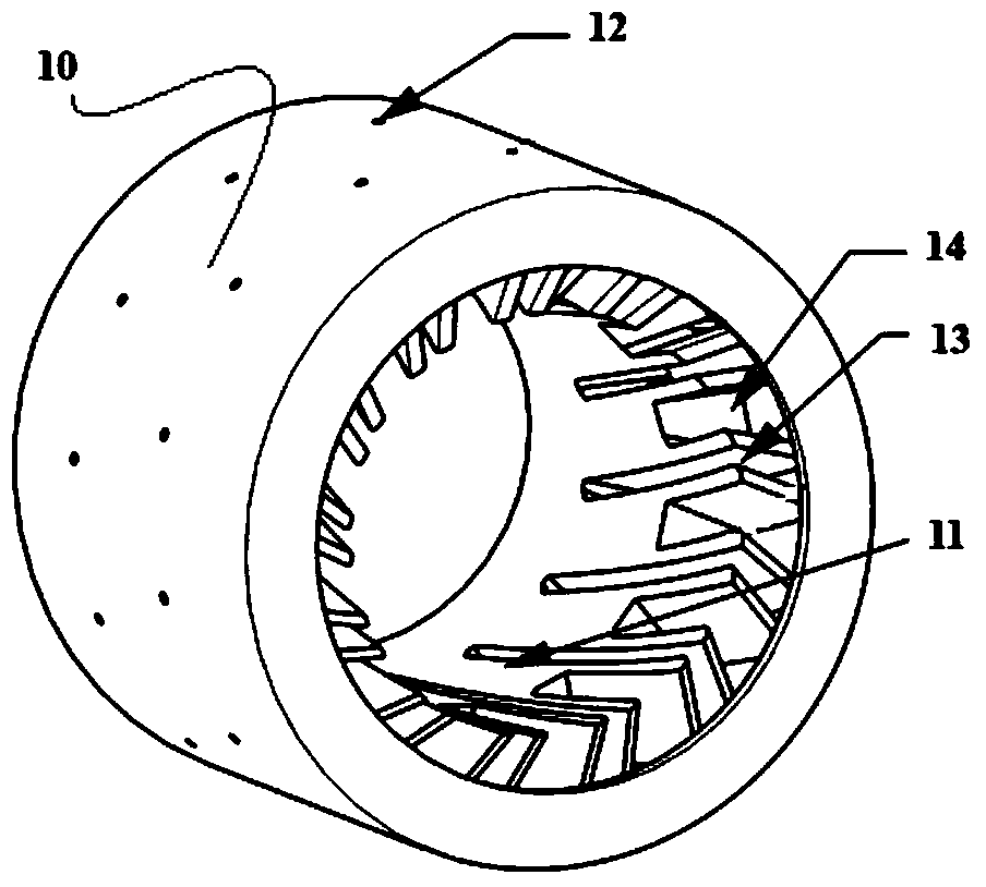
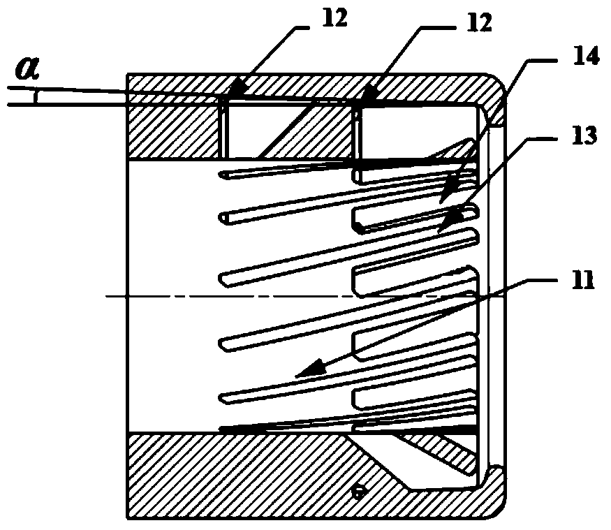
[0040] Such as Figure 1 to Figure 3As shown, this embodiment provides an axial oil collector, including a cylindrical oil collector body 11, one end of the oil collector body 11 is the oil inlet end; The oil collecting grooves are arranged in the circumferential direction, and one end of the oil collecting grooves is connected to the opening of the oil inlet end of the oil collecting ring body to form an oil collecting inlet, and the other end of the oil collecting grooves is not connected to form an oil collecting retaining wall; The bottom of the oil collecting groove is provided with an oil delivery hole 12 that runs through the wall of the oil collecting ring body 11; the oil collecting grooves are all inclined to the same side; The distance from the oil retaining wall to the oil receiving inlet is greater than the distance from the oil receiving retaining wall of the short oil receiving groove 14 to the oil receiving inlet; the wall between the long oil receiving groove ...

Embodiment 2

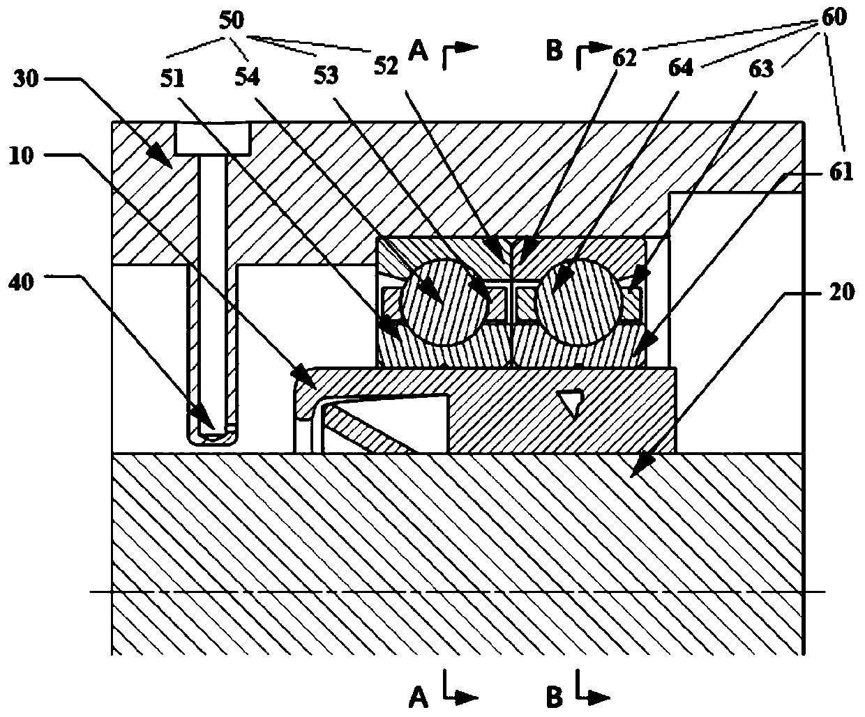
[0045] Such as Figures 1 to 7 As shown, this embodiment provides a lubricating device under the main bearing ring of an aeroengine, including the axial oil collector 10 in Embodiment 1, and also includes: a main shaft 20, a bearing, a bearing seat 30 sleeved outside the bearing, and a The oil supply nozzle 40 on the bearing seat 30 and connected to the oil supply path; the oil supply nozzle 40 penetrates into the bearing seat 30; the axial oil collection ring 10 is set on the main shaft 20, and the bearing is sleeved on the axial oil collection ring 10, Both the axial oil collector ring 10 and the bearing can rotate synchronously with the main shaft 20 .

[0046] Bearing comprises front bearing 50 and rear bearing 60, and front bearing 50 comprises front bearing inner ring 51, front bearing outer ring 52 and is located between front bearing inner ring 51 and front bearing outer ring 52 and is held by front bearing cage 53. The front bearing rolling body 54; the rear bearing ...

Embodiment 3

[0051] This embodiment provides a method for lubricating under the main bearing ring of an aero-engine, which is realized by using the device in Embodiment 2, and specifically includes the following steps:

[0052] Lubricating oil is sprayed from the oil supply nozzle to the oil inlet end of the axial oil collection ring, and the injection direction of the oil supply nozzle is determined by Figure 7 The velocity triangle shown is determined. The lubricating oil enters the long and short oil collecting grooves tangentially to the tip of the oil collecting blade. to the inner wall of the axial oil collector ring, the lubricating oil with kinetic energy tends to flow axially along the inner wall of the axial oil collector ring, and at the same time, the groove depth of the oil receiver groove from the oil receiver inlet to the oil receiver retaining wall gradually increases , the lubricating oil flowing against the wall is accelerated by the centrifugal force component and flows...


PUM


Abstract

The invention provides an axial oil collecting ring and an inner-ring lubricating device and method of an aviation engine main bearing. The axial oil collecting ring comprises a cylindrical oil collecting ring body, a plurality of oil collecting grooves arranged in the circumferential direction are formed in the inner wall of the oil collecting ring body, one end of each oil collecting groove penetrates to the opening of the oil inlet end of the oil collecting ring body to form an oil collecting inlet, and the other end of each oil collecting groove does not penetrate to form an oil collectingbaffle wall; an oil conveying hole penetrating through the wall surface of the oil collecting ring body is formed in the position, near the corresponding oil collecting baffle wall, of each oil collecting groove; the inner-ring lubricating device comprises the axial oil collecting ring, a main shaft, a bearing, a bearing seat sleeving the bearing and an oil supply nozzle which is arranged on thebearing seat and connected with an oil supply path and penetrates into the bearing seat; the axial oil collecting ring sleeves the main shaft, the bearing sleeves the axial oil collecting ring, and both the axial oil collecting ring and the bearing can rotate synchronously along with the main shaft. According to the axial oil collecting ring and the inner-ring lubricating device and method of theaviation engine main bearing, quantitative distribution of lubricating oil can be realized under high oil collection efficiency, lubrication and cooling requirements of high-speed rolling bearings aremet, and safety and reliability of the bearings are improved.

Description

technical field [0001] The invention belongs to the field of oil supply lubrication for aero-engine bearings, and relates to a lubricating device and method for an axial oil collector ring and an aero-engine main bearing ring. Background technique [0002] The speed of the main shaft of the aeroengine increases with the improvement of engine performance and output power, and then the DN value of the bearing increases accordingly, resulting in an increase in the contact angle of the inner ring of the bearing and a decrease in the contact angle of the outer ring, and at the same time, the spin speed of the rolling elements increases. The resulting increase in bearing heat generation may accelerate bearing damage and failure. The aero-engine lubrication system can provide an appropriate amount of lubricating oil to the bearings supporting the rotor to reduce the friction and wear between the various components and remove the generated heat in time. The traditional spray lubric...

Claims


Application Information

Patent Timeline
Patent Type & Authority Applications(China)
IPC IPC(8): F02C7/06F02C7/16
CPCF02C7/06F02C7/16
Inventor 吕亚国姜乐刘振侠张丽芬刘振刚吴丁毅朱鹏飞
Owner 西安瑞谱捷特动力技术有限公司
Why Eureka
Try Eureka