Lubricating device and method for an axial oil collector ring and an aeroengine main bearing ring
An oil scavenger, axial technology, applied in the direction of engine lubrication, engine components, engine cooling, etc., can solve the problems of simple injection lubrication structure, achieve high oil scavenging efficiency, reduce splashes, and prolong service life.
- Summary
- Abstract
- Description
- Claims
- Application Information
AI Technical Summary
Problems solved by technology
Method used
Image
Examples
Embodiment 1
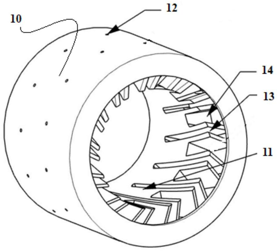
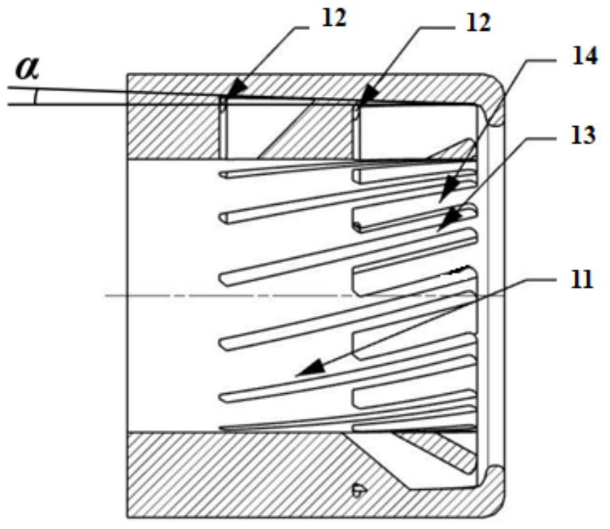
[0040] Such as Figure 1 to Figure 3As shown, this embodiment provides an axial oil collector, including a cylindrical oil collector body 11, one end of the oil collector body 11 is the oil inlet end; The oil collecting grooves are arranged in the circumferential direction, and one end of the oil collecting grooves is connected to the opening of the oil inlet end of the oil collecting ring body to form an oil collecting inlet, and the other end of the oil collecting grooves is not connected to form an oil collecting retaining wall; The bottom of the oil collecting groove is provided with an oil delivery hole 12 that runs through the wall of the oil collecting ring body 11; the oil collecting grooves are all inclined to the same side; The distance from the oil retaining wall to the oil receiving inlet is greater than the distance from the oil receiving retaining wall of the short oil receiving groove 14 to the oil receiving inlet; the wall between the long oil receiving groove ...
Embodiment 2
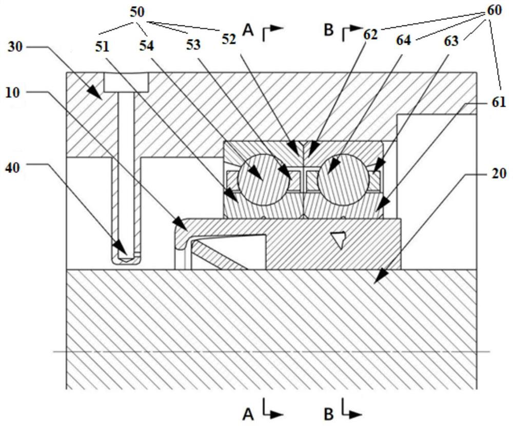
[0045] Such as Figures 1 to 7 As shown, this embodiment provides a lubricating device under the main bearing ring of an aeroengine, including the axial oil collector 10 in Embodiment 1, and also includes: a main shaft 20, a bearing, a bearing seat 30 sleeved outside the bearing, and a The oil supply nozzle 40 on the bearing seat 30 and connected to the oil supply path; the oil supply nozzle 40 penetrates into the bearing seat 30; the axial oil collection ring 10 is set on the main shaft 20, and the bearing is sleeved on the axial oil collection ring 10, Both the axial oil collector ring 10 and the bearing can rotate synchronously with the main shaft 20 .
[0046] Bearing comprises front bearing 50 and rear bearing 60, and front bearing 50 comprises front bearing inner ring 51, front bearing outer ring 52 and is located between front bearing inner ring 51 and front bearing outer ring 52 and is held by front bearing cage 53. The front bearing rolling body 54; the rear bearing ...
Embodiment 3
[0051] This embodiment provides a method for lubricating under the main bearing ring of an aero-engine, which is realized by using the device in Embodiment 2, and specifically includes the following steps:
[0052] Lubricating oil is sprayed from the oil supply nozzle to the oil inlet end of the axial oil collection ring, and the injection direction of the oil supply nozzle is determined by Figure 7 The velocity triangle shown is determined. The lubricating oil enters the long and short oil collecting grooves tangentially to the tip of the oil collecting blade. to the inner wall of the axial oil collector ring, the lubricating oil with kinetic energy tends to flow axially along the inner wall of the axial oil collector ring, and at the same time, the groove depth of the oil receiver groove from the oil receiver inlet to the oil receiver retaining wall gradually increases , the lubricating oil flowing against the wall is accelerated by the centrifugal force component and flows...
PUM
 Abstract
Description
Claims
Application Information
 - R&D
- Intellectual Property
- Life Sciences
- Materials
- Tech Scout
- Unparalleled Data Quality
- Higher Quality Content
- 60% Fewer Hallucinations
Browse by: Latest US Patents, China's latest patents, Technical Efficacy Thesaurus, Application Domain, Technology Topic, Popular Technical Reports.
© 2025 PatSnap. All rights reserved.Legal|Privacy policy|Modern Slavery Act Transparency Statement|Sitemap|About US| Contact US: help@patsnap.com


