Power transmission line distributed fault diagnosis system and method

A fault diagnosis system and transmission line technology, applied in the transmission system, digital transmission system, fault location, etc., can solve the problems of continuous deployment obstacles, reliability and stability impact, difficult coordination and expansion of single application, etc., to improve Horizontal scalability, seamless adaptation, improvement of debugging operation and maintenance efficiency and system stability

Active Publication Date: 2020-02-04
NARI TECH CO LTD +1
View PDF5 Cites 3 Cited by
  • Summary
  • Abstract
  • Description
  • Claims
  • Application Information

AI Technical Summary

Problems solved by technology

The excellent performance of distributed traveling waves in transmission line fault location has led to the rapid development of distributed traveling waves. There are many manufacturers of transmission line fault diagnosis and monitoring terminals, and the diagnostic and positioning function modules have been moved to the central station. The central station needs to have horizontal expansion capabilities. Simplify application deployment, a

Method used


Image

  • Power transmission line distributed fault diagnosis system and method
  • Power transmission line distributed fault diagnosis system and method
  • Power transmission line distributed fault diagnosis system and method

Examples


Embodiment 1

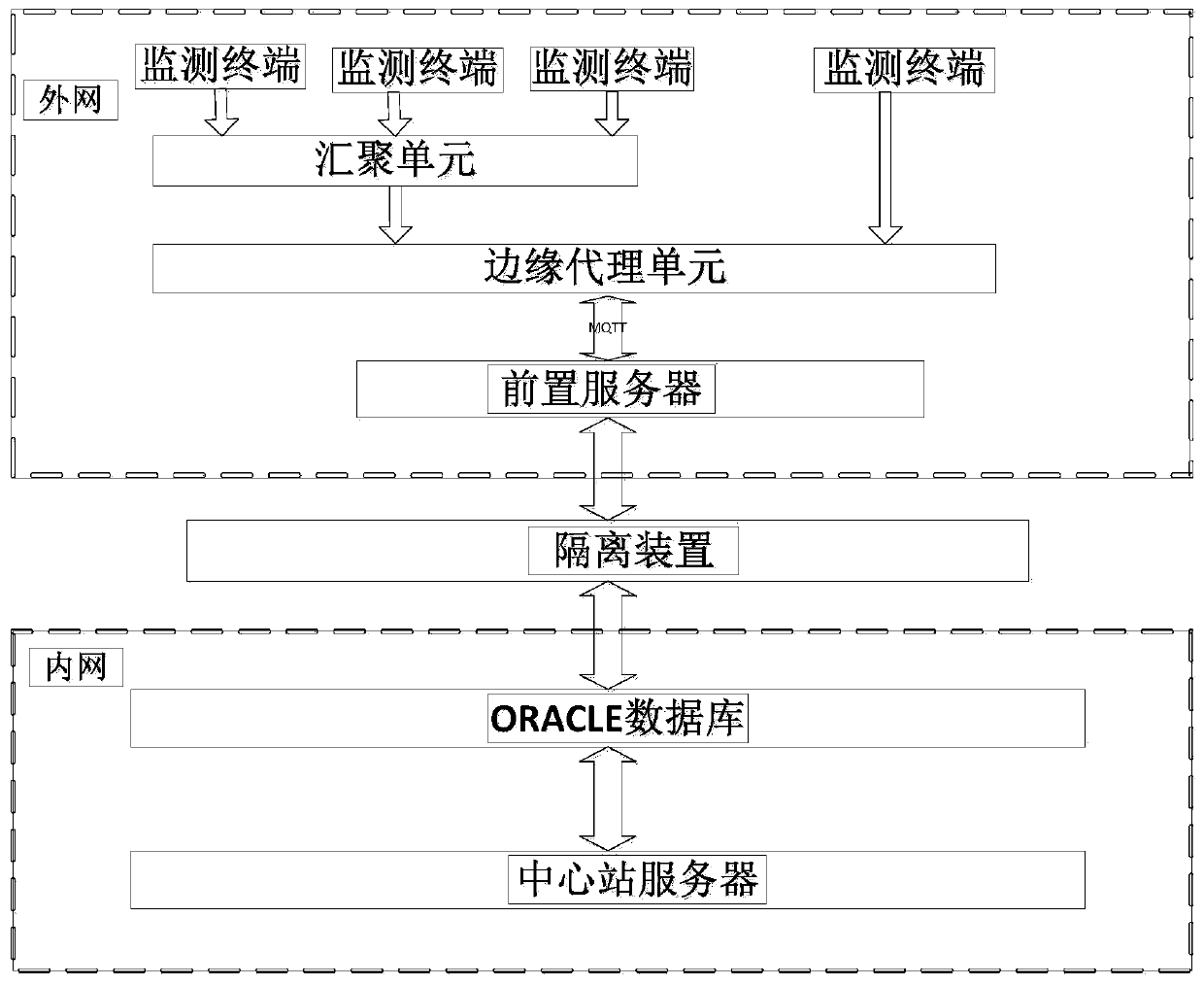
[0060] Such as figure 1 As shown, the embodiment of the present invention provides a distributed fault diagnosis system for transmission lines, including a monitoring terminal, a front server, and a central station server, and the central station server includes a communication microservice unit, a core microservice unit, and a fault location microservice unit;

[0061] In the specific application process of the transmission line distributed fault diagnosis system in the embodiment of the present invention, the monitoring terminal is deployed on various poles and towers, and is used to collect data such as traveling wave current, fault current traveling wave data, and clock data;

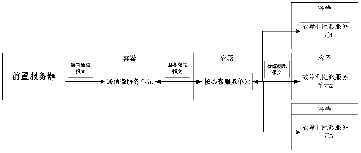
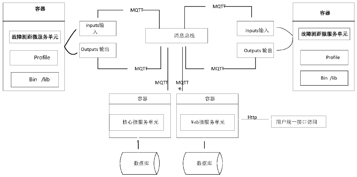
[0062] Such as Figure 2-4 As shown, the front-end server receives the data message (such as device traveling wave current data message) sent by the monitoring terminal, and stores it in a database, such as an oracle database; in a specific implementation manner of an embodiment of the present inve...

Embodiment 2

[0094] The difference between the embodiment of the present invention and embodiment 1 is:

[0095] A converging unit and an edge agent unit connected in sequence are arranged between the monitoring terminal and the front-end server;

[0096] The convergence unit is also connected to the monitoring terminal, so that multiple monitoring terminals converge to the convergence unit;

[0097]The edge proxy unit is also connected to the front-end server to realize protocol conversion and interconnection.

[0098] An isolation device is provided between the fault diagnosis unit and the front-end server, which mainly realizes the physical isolation of the monitoring terminal and the business system (that is, the communication micro-service unit, the core micro-service unit and the fault ranging micro-service unit) to prevent illegal links Access through the intranet.

[0099] Example 2

[0100] An embodiment of the present invention provides a distributed fault diagnosis method for...


PUM


Abstract

The invention discloses a distributed fault diagnosis system and method for a power transmission line. The distributed fault diagnosis system comprises a monitoring terminal, a front server and a central station server. The central station server comprises a communication micro-service unit, a core micro-service unit and a fault distance measurement micro-service unit; the front server receives the data message sent by the monitoring terminal and stores the data message in a database; the communication micro-service unit reads the data message from the database and forms a file; the core micro-service unit receives an interaction message sent by the communication micro-service unit, finds out a corresponding fault distance measurement micro-service unit based on ID information in the interaction message, and sends a file obtained from the communication micro-service unit to the fault distance measurement micro-service unit; and the fault distance measurement micro-service unit completes fault diagnosis based on the received file. According to the invention, the system access time of fault distance measurement terminals (namely fault distance measurement micro-service units) of different manufacturers can be greatly shortened, and the operation and maintenance efficiency is improved.

Description

technical field [0001] The invention belongs to the technical field of power grid operation and maintenance, and in particular relates to a distributed fault diagnosis system and method for transmission lines. Background technique [0002] Overhead transmission lines have many points, long lines, wide areas, and complex network structures. They are distributed in the wild with harsh environments, causing great difficulties for equipment inspections. During actual operation, they often suffer from natural disasters (lightning strikes, rainstorms, Extremely bad weather such as heavy snow, strong wind, bird damage and other factors) and external damage (various constructions, traffic accidents, human-made theft, etc.), cause the grounding short circuit tripping of the line, or even the line is broken, causing the line to be paralyzed and causing a large area The power outages have brought certain impacts on the stability, safety, economy, efficiency and high-quality operation of ...

Claims


Application Information

Patent Timeline
IPC IPC(8): H04L12/24H04L29/08H04L29/06G01R31/08
CPCH04L41/0677H04L67/025H04L67/34H04L69/08G01R31/085H04L63/0209H04L67/565
Inventor 饶丹周华良宋斌李友军李临风张恒吴通华王军
Owner NARI TECH CO LTD
Why Eureka
Try Eureka