
A kind of steel casing machine

A technology of casing machine and casing frame, which is applied in the field of building material processing, can solve the problems of loss of bonding force between steel bars and concrete, concrete cracking, high cost, etc., and achieves the advantages of smooth transportation, precise control, and precise rotation angle Effect

Active Publication Date: 2020-12-08
山东博通塑胶有限公司
View PDF9 Cites 0 Cited by
  • Summary
  • Abstract
  • Description
  • Claims
  • Application Information

AI Technical Summary

Problems solved by technology

But when the rebar corrodes, the rust spreads, cracking the concrete and losing the bond between the rebar and concrete
Especially at the junction between beams, columns and floors in buildings, in order to avoid the loss of bonding force with concrete due to corrosion of steel bars, the most advanced and effective treatment method is to place steel bars at the junctions between beams, columns and floors For casing, the casing generally adopts stainless steel casing. Due to the high cost of stainless steel casing, the cost of casing the entire steel bar will be very high. Therefore, the most critical steel bar is located at the junction between the beam column and the floor. Casing is performed because this position is not critical, and loss of bonding force will greatly affect the strength and service life of the building
At present, the structure of steel casing is rarely used in the market, and there is no special equipment for steel casing

Method used


Image

  • A kind of steel casing machine
  • A kind of steel casing machine
  • A kind of steel casing machine

Examples


Embodiment Construction

[0025] The present invention will be further described in detail below in conjunction with the accompanying drawings and examples. The following examples are explanations of the present invention and the present invention is not limited to the following examples.

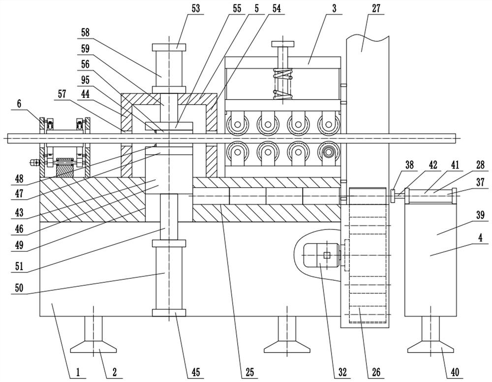
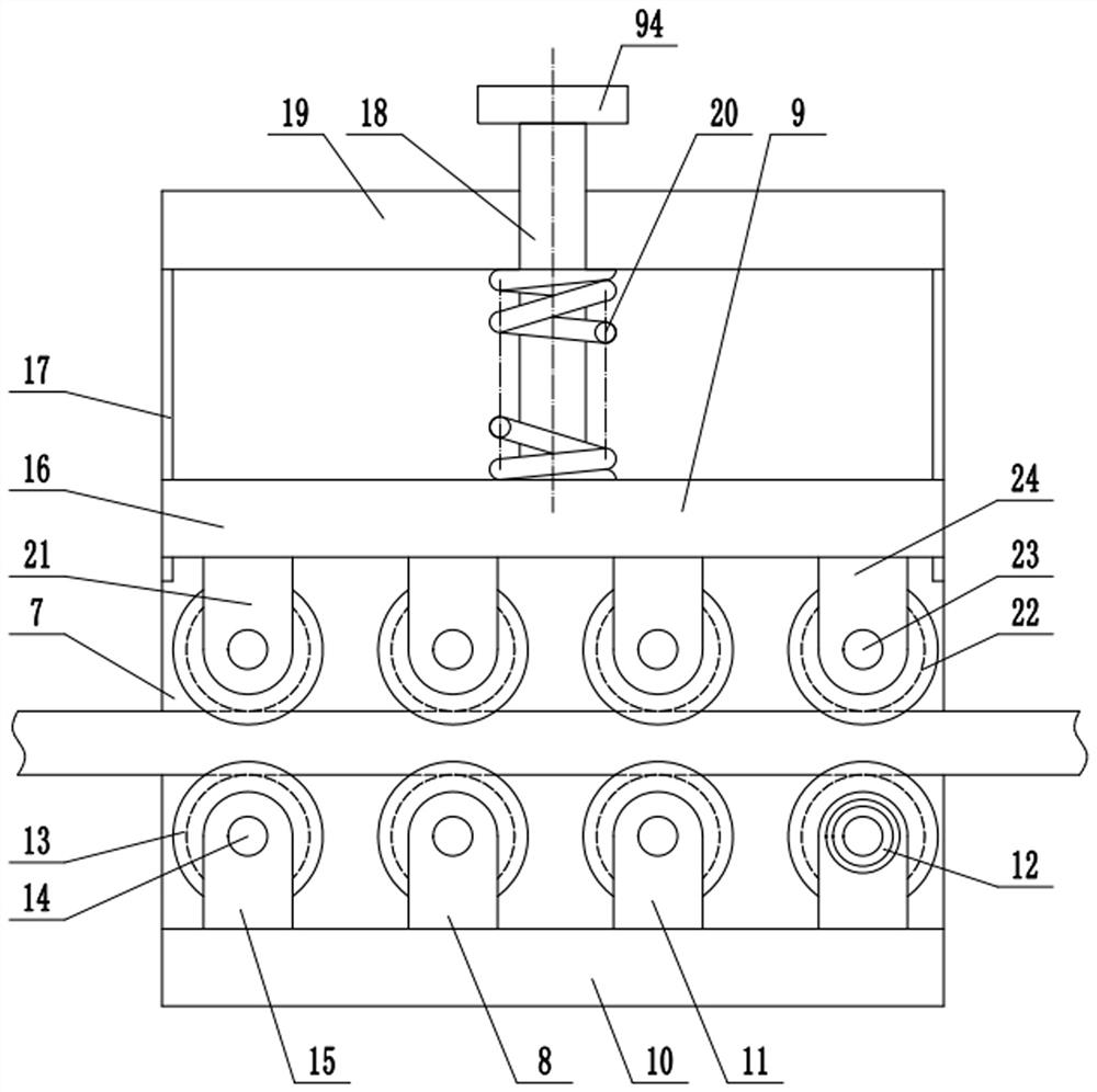
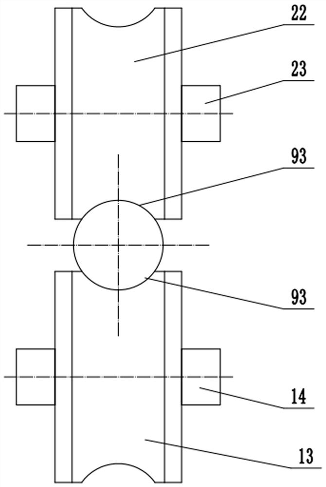
[0026] Such as figure 1 , figure 2 , image 3 , Figure 4 , Figure 5 , Figure 6 , Figure 7 , Figure 8 , Figure 9 , Figure 10 and Figure 11As shown, a steel casing machine, which includes a casing frame 1, a casing frame support foot 2, a steel bar feeding straightening device 3, a casing feeding device 4, a casing device 5, and an eccentric engagement device 6. The lower end of the casing frame 1 is provided with a casing frame supporting foot 2, and the steel bar feeding straightening device 3 includes a feeding support 7, a lower feeding straightening mechanism 8, an upper feeding straightening Mechanism 9, the feeding support 7 is fixed on the casing frame 1, and the lower feeding straightening ...


PUM


Abstract

The invention provides a steel bar sleeving machine, and belongs to the technical field of building material machining. The steel bar sleeving machine comprises a steel bar feeding and straightening device, a sleeve pipe feeding device, a sleeve pipe device and an eccentric clamping device. The steel bar feeding and straightening device comprises a lower feeding and straightening mechanism and anupper feeding and straightening mechanism. The sleeve pipe feeding device comprises a feeding channel, a feeding disc assembly, a sleeve pipe storage assembly and a pushing device. The sleeve pipe device comprises a sleeve pipe lower supporting assembly and a sleeve pipe upper supporting assembly. The eccentric clamping device comprises a left clamping assembly, a right clamping assembly and a clamping drive assembly, and the left clamping assembly and the right clamping assembly are arranged symmetrically. According to the steel bar sleeving machine, automatic sleeving can be achieved at thedesignated spots of steel bars, sleeve pipes and the steel bars can be clamped, the sleeve pipes are effectively prevented from moving on the steel bars, the structure is reasonable, and the automation degree is high.

Description

technical field [0001] The invention relates to the technical field of building material processing, in particular to a steel bar casing machine. Background technique [0002] Reinforced concrete refers to a composite material formed by adding steel mesh, steel plates or fibers to work together to improve the mechanical properties of concrete. It is the most common form of reinforced concrete. The reason why reinforced concrete can work together is determined by its own material properties. First of all, steel bars and concrete have approximately the same linear expansion coefficient, and excessive stress will not be generated due to different environments. Secondly, there is a good bond between the steel bar and the concrete. Sometimes the surface of the steel bar is also processed into spaced ribs (called deformed steel bars) to improve the mechanical engagement between the concrete and the steel bar. However, this is still not enough to transmit the steel bar and the ste...

Claims


Application Information

Patent Timeline
Patent Type & Authority Patents(China)
IPC IPC(8): B21F15/00B21F1/02B21F23/00
CPCB21F1/02B21F15/00B21F23/00
Inventor 潘萍儿
Owner 山东博通塑胶有限公司
Learn More