Gas monitoring device and method for carbon dioxide flooding gas channeling
A carbon dioxide and gas monitoring technology, applied in the fields of fluid production, earthwork drilling, wellbore/well components, etc., can solve the problems of low detection sensitivity, poor stability, poor selectivity, etc.
- Summary
- Abstract
- Description
- Claims
- Application Information
AI Technical Summary
Problems solved by technology
Method used
Image
Examples
no. 1 approach
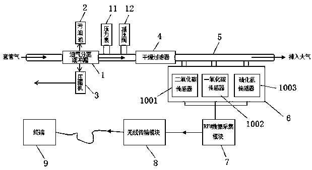
[0026] Such as figure 1 As shown, the first embodiment of the present invention relates to a gas monitoring device for carbon dioxide driving gas channeling, which includes an oil-gas separation buffer tank 1, and the oil-gas separation buffer tank 1 has three tank ports, which are respectively an oil inlet, an outlet An oil port and an air outlet, the oil inlet is connected to the casing, the oil outlet is opened at the bottom of the tank and connected to the dirty oil pool 2, and the air outlet is opened at the top of the tank and connected to two gas pipelines, one of which is The gas pipeline is connected to the inlet of the compressor 3, the outlet of the compressor 3 is connected to the downstream gathering and transportation pipeline, another gas transmission line is connected to the inlet of the drier filter 4 through the pipeline, and the outlet of the drier filter 4 is connected to the exhaust pipeline 5, and the exhaust gas The pipe wall of the pipeline 5 is connect...
no. 2 approach
[0035] A gas monitoring device for carbon dioxide driving and gas channeling, which includes an oil-gas separation buffer tank 1. The oil-gas separation buffer tank 1 has three tank ports, which are respectively an oil inlet, an oil outlet and a gas outlet. The oil inlet is connected to the sleeve The oil outlet is opened at the bottom of the tank and connected to the dirty oil pool 2, and the gas outlet is opened at the top of the tank and connected to two gas pipelines, one of which is connected to the inlet of compressor 3 and the outlet of compressor 3 Connect the downstream gathering and transportation pipeline, and another gas transmission pipeline is connected to the inlet of the drier filter 4 through the pipeline, and the outlet of the drier filter 4 is connected to the exhaust pipeline 5, and the pipe wall of the exhaust pipeline 5 is connected to the sampler through a bypass pipeline 6. A gas sensor group capable of detecting the concentration of various gases is ins...
no. 3 approach
[0041] Different from the first embodiment, the pipeline between the oil-gas separation buffer tank 1 and the dry filter 4 is equipped with a pressure gauge 11 and a pressure reducing valve 12 from upstream to downstream, and the pressure gauge 11 is used to detect the separation of the oil-gas separation buffer tank 1 If the gas pressure exceeds the preset value, the pressure reducing valve 12 is opened to ensure the safe operation of the entire monitoring device.
[0042] In order to realize the accurate real-time transmission of the detection data of the monitoring device and simplify the equipment, the concentration of various gases collected by the RTU data acquisition module 7 is transmitted to the terminal 9 through the wireless transmission module 8, and the terminal 9 is a computer.
[0043] In order to meet the requirements of safety and environmental protection, the compressor 3 is a two-stage compressor, which is composed of a low-pressure stage and a high-pressure ...
PUM
 Abstract
Description
Claims
Application Information
 - R&D
- Intellectual Property
- Life Sciences
- Materials
- Tech Scout
- Unparalleled Data Quality
- Higher Quality Content
- 60% Fewer Hallucinations
Browse by: Latest US Patents, China's latest patents, Technical Efficacy Thesaurus, Application Domain, Technology Topic, Popular Technical Reports.
© 2025 PatSnap. All rights reserved.Legal|Privacy policy|Modern Slavery Act Transparency Statement|Sitemap|About US| Contact US: help@patsnap.com

