
Gas burner capable of enhancing ultraviolet light signal strength

A signal strength, gas burner technology, applied in the burner, combustion method, combustion type and other directions, can solve the problems of shortening the distance between the ultraviolet flame detection probe and the flame, unstable operation of the ultraviolet flame detector, etc., to solve the problem of unstable work. , the effect of shortening the distance

Pending Publication Date: 2020-02-07
郑时伟
View PDF0 Cites 0 Cited by
  • Summary
  • Abstract
  • Description
  • Claims
  • Application Information

AI Technical Summary

Problems solved by technology

[0006] The purpose of the present invention is to provide a gas burner with enhanced ultraviolet signal intensity, use the flame detection probe to cool the air and mix combustion with a small amount of gas, form a flame area in advance at the near end of the gas burner, shorten the distance between the ultraviolet flame detection probe and the flame The distance between them solves the problem of unstable work of the ultraviolet flame detector caused by the above situation

Method used


Image

  • Gas burner capable of enhancing ultraviolet light signal strength
  • Gas burner capable of enhancing ultraviolet light signal strength
  • Gas burner capable of enhancing ultraviolet light signal strength

Examples


Embodiment 1

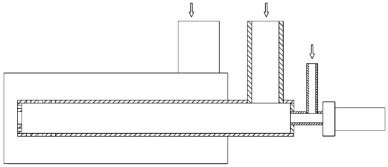
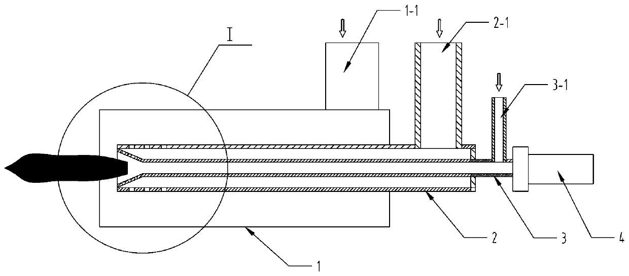
[0021] Embodiment 1, the present invention includes a burner housing 1, a gas channel 2, an ultraviolet flame detection cooling air channel 3 and an ultraviolet flame detection probe 4, the ultraviolet flame detection cooling air channel 3 extends into the gas channel 2, and The end of the detection cooling air channel 3 is provided with a through hole that communicates with the gas channel 2, and the ultraviolet flame detection cooling air is guided to the end of the ultraviolet flame detection cooling air channel 3 and mixed with gas to form a bright flame, shortening the distance between the ultraviolet flame detection probe 4 and the gas. distance between flames. refer to Figure 1 to Figure 5 .

Embodiment 2

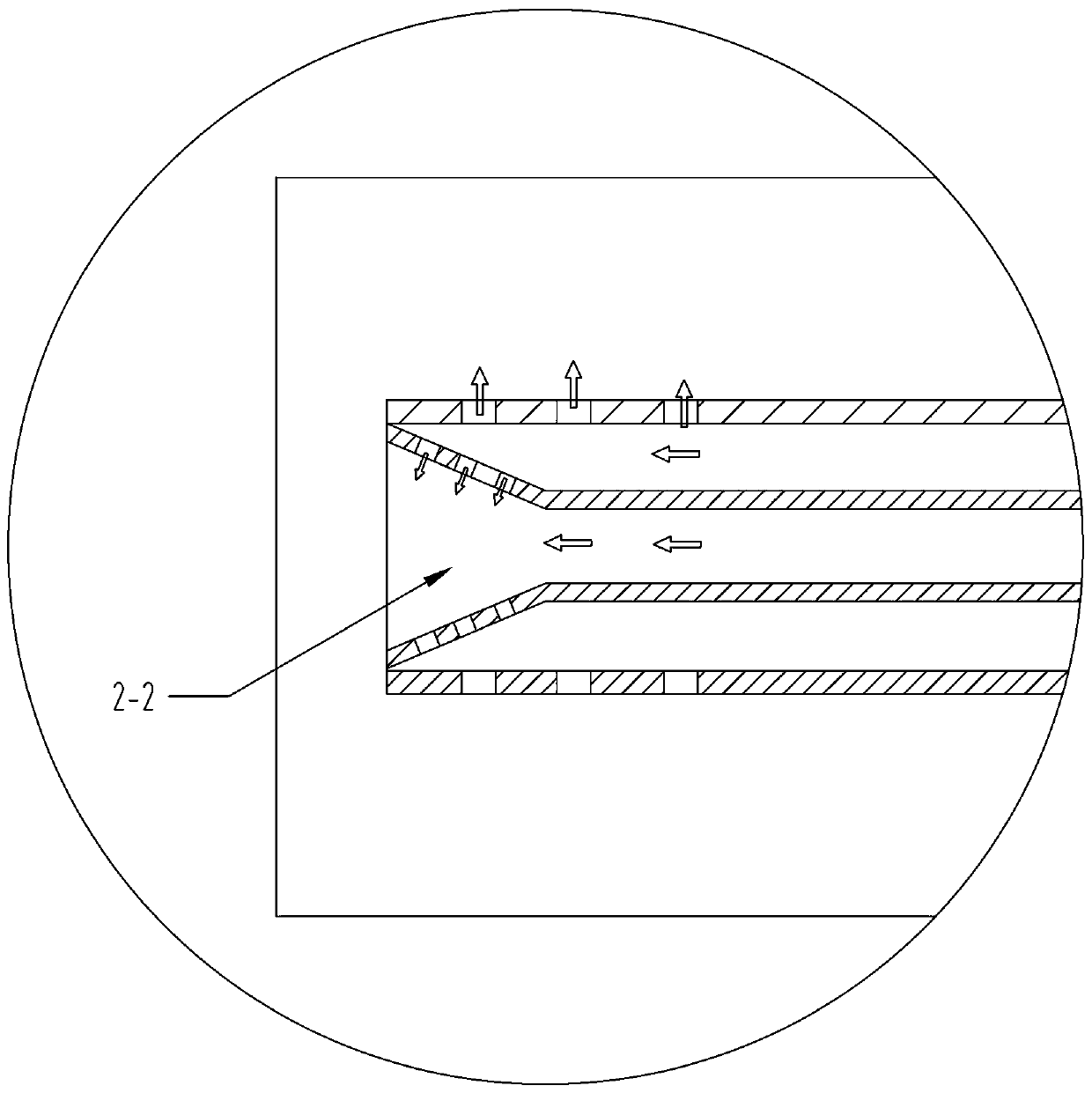
[0022] Embodiment 2, the burner casing 1 is provided with a gas passage 2, a primary air passage is formed in the burner casing 1 outside the gas passage 2, and a primary air inlet 1-1 is opened, and the gas passage 2 extends out of the burner The housing 1 is provided with one end of the primary air inlet 1-1, and a gas inlet 2-1 is provided on the side wall of the protruding part. The gas passage 2 is provided with an ultraviolet flame detection cooling air passage 3, and an ultraviolet flame detection cooling air passage 3. One end protrudes from the gas channel 2 to connect with the ultraviolet flame detection probe 4, and an ultraviolet flame detection cooling air inlet 3-1 is provided on the side wall of the extended part, and the other end is set as a bell mouth 2-2, and the bell mouth The outer wall of the big end of 2-2 is fixedly connected with the inner wall of the end of the gas channel 2, and the side wall of the bell mouth 2-2 is provided with a through hole commu...


PUM


Abstract

The invention discloses a gas burner capable of enhancing ultraviolet light signal strength. The technical problems that due to an existing gas burner structure, the distance between a flame detectionprobe and a flame is too large, the ultraviolet light strength is too weak, and an ultraviolet light flame detector is not stable in work are solved. According to the technical scheme, the gas burnercomprises a burner shell (1), a gas channel (2) and an ultraviolet flame detection cooling air channel (3) and an ultraviolet flame detection probe (4). The ultraviolet flame detection cooling air channel (3) extends into the gas channel (2), a through hole communicating with the gas channel (2) is formed in the tail end of the ultraviolet flame detection cooling air channel (3), ultraviolet flame detection cooling air is led into the tail end of the ultraviolet flame detection cooling air channel (3) to be mixed with gas to be combusted, bright flames are formed, and the distance between theultraviolet flame detection probe (4) and the flame can be shortened.

Description

technical field [0001] The invention relates to a gas burner with enhanced ultraviolet signal intensity. Background technique [0002] With the increase of energy costs, in order to reduce energy consumption and save production costs, regenerative burners are becoming more and more popular in the aluminum melting furnace industry, and diffusion regenerative burners have low burning loss, uniform furnace temperature, and low nitrogen oxides. A series of advantages, such as less emissions, account for an increasing proportion of regenerative burners. [0003] Flame detection is the most important safety detection measure when the regenerative burner is running. There are two general flame detection methods at present, one is an ion needle flame detector, and the other is an ultraviolet flame detector. [0004] The basic principle of ultraviolet flame detection is: the open flame will produce ultraviolet rays, and the ultraviolet flame detector can determine whether there is ...

Claims


Application Information

Patent Timeline
Patent Type & Authority Applications(China)
IPC IPC(8): F23D14/02F23D14/46F23D14/48
CPCF23D14/02F23D14/46F23D14/48
Inventor 郑时伟
Owner 郑时伟
Learn More