Missile interference identification algorithm

An aircraft bomb and algorithm technology is applied in the field of airborne missile flight test data analysis to achieve the effect of improving identification accuracy and reducing phase lag

Active Publication Date: 2020-02-07
SHANGHAI AEROSPACE CONTROL TECH INST
View PDF4 Cites 1 Cited by
  • Summary
  • Abstract
  • Description
  • Claims
  • Application Information

AI Technical Summary

Problems solved by technology

[0004] The problem to be solved by the technology of the present invention is to use the angular velocity information containing high-frequency noise obtained from the flight test inertial measurement device, after data preprocessing, to identify aircraft-bullet interference, so as to obtain aircraft-bullet interference

Method used


Image

  • Missile interference identification algorithm
  • Missile interference identification algorithm
  • Missile interference identification algorithm

Examples


Embodiment Construction

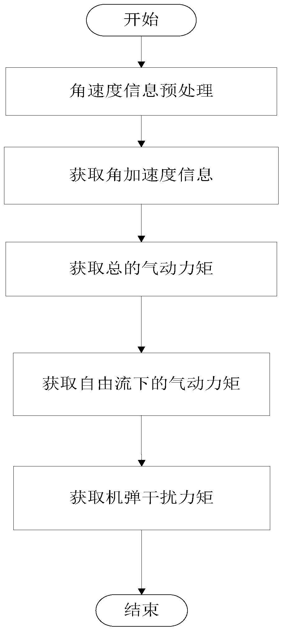
[0033] The specific embodiments of the machine-bomb interference identification algorithm provided by the present invention are described below:

[0034] First, the definitions of the coordinate systems and angles involved are introduced in conjunction with the accompanying drawings.

[0035] 1. Projectile coordinate system oxyz

[0036] The coordinate origin o is located at the center of mass of the missile body, the ox axis is along the longitudinal axis of the missile body, and it is positive from the tail to the head. The oy axis is in the longitudinal symmetry plane of the missile including the ox axis and is perpendicular to the ox axis, and it is positive when it points upward. The oz axis is the same as The ox and oy axes form a right-handed coordinate system.

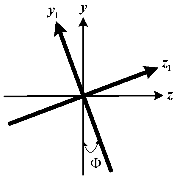
[0037] 2. Projectile body rotation coordinate system ox 1 y 1 z 1

[0038] The coordinate origin o is located at the center of mass of the projectile, ox 1 The axis is along the longitudinal axis of the p...


PUM


Abstract

The invention discloses a missile interference identification algorithm, which belongs to the field of missile flight test data analysis, and comprises the following steps: 1, preprocessing angular velocity information acquired by an inertial measurement device, including unit transformation and high-frequency noise filtering; 2, selecting a proper time interval according to the processed angularvelocity information, and resolving angular acceleration information; 3, according to the angular acceleration information and the moment of inertia of the missile, solving the total moment componentof each axis under the missile system; 4, according to the Mach number, the synthetic attack angle, the airflow roll angle, the mass center, the rudder deflection angle and other information, solvingtorque components of all shafts under a missile system under the free flow of the missile; and 5, subtracting the moment flowing down freely from the total moment of each shaft under the projectile system to obtain a projectile disturbance moment component of each shaft under the projectile system. According to the missile interference identification algorithm, high-frequency signals are filteredout in a targeted mode, and phase lag is reduced as much as possible, and it is ensured that the processed angular velocity information can be used for extracting mechanical missile interference.

Description

technical field [0001] The invention relates to the field of airborne missile flight test data analysis, in particular to an airborne missile interference identification algorithm, in particular to an aerodynamic interference identification method for an airborne missile ejection separation section of an internal or external catapult launcher. Background technique [0002] In order to meet the diverse needs of combat aircraft hang points and the needs of stealth performance, the launch method of airborne missiles has developed from the traditional sliding rail type to the catapult type. Due to the short distance between the missile and the carrier aircraft, a strong interference force and interference torque will be generated between the missile and the carrier aircraft, forming a more complex flow field environment. Obtaining accurate missile jamming is particularly important for the safe ejection and separation of missiles. [0003] At present, the CTS test is mainly used...

Claims


Application Information

Patent Timeline
Patent Type & Authority Applications(China)
IPC IPC(8): G06F17/10G01P3/00G01M9/02
CPCG06F17/10G01P3/00G01M9/02Y02T90/00
Inventor 叶赛仙仲科伟张晓峰彭一洋蒋虎超朱雯雯朱成成
Owner SHANGHAI AEROSPACE CONTROL TECH INST
Why Eureka
Try Eureka