
Wafer cleaning method

A wafer and cleaning solution technology, applied in electrical components, semiconductor/solid-state device manufacturing, circuits, etc., can solve the problems of moving to the whole wafer, incomplete wafer cleaning, poor wafer cleanliness, etc. High yield, good cleaning effect and less contamination

Inactive Publication Date: 2020-02-07
SHANGHAI HUALI MICROELECTRONICS CORP
View PDF17 Cites 3 Cited by
  • Summary
  • Abstract
  • Description
  • Claims
  • Application Information

AI Technical Summary

Problems solved by technology

In the prior art, the equipment for cleaning wafers usually adopts a chip brushing machine. There are two common cleaning methods. One is to place the wafer on a rotating table and rotate it. The nano nozzle of the chip cleaning machine is located on the wafer Directly above the circle and spray the cleaning liquid directly towards the center of the wafer, using the centrifugal force generated during the rotation to make the cleaning liquid clean the entire surface of the wafer, but this method does not clean the edge of the wafer thoroughly, and pollutants such as particles will Residues on the wafer form defects, which will easily affect the subsequent process; secondly, the wafer is placed on the rotary table and rotated, and the nano-spray head of the chip brushing machine is sprayed from one side of the wafer and is sprayed by the side of the wafer. The edge moves to the other side of the wafer and sprays cleaning fluid, which can easily cause contaminants such as particles to move to the entire wafer, making the entire wafer less clean

Method used


Image

  • Wafer cleaning method
  • Wafer cleaning method
  • Wafer cleaning method

Examples


Embodiment Construction

[0025] The specific implementation manner of the present invention will be described in more detail below with reference to schematic diagrams. Advantages and features of the present invention will be apparent from the following description and claims. It should be noted that all the drawings are in a very simplified form and use imprecise scales, and are only used to facilitate and clearly assist the purpose of illustrating the embodiments of the present invention.

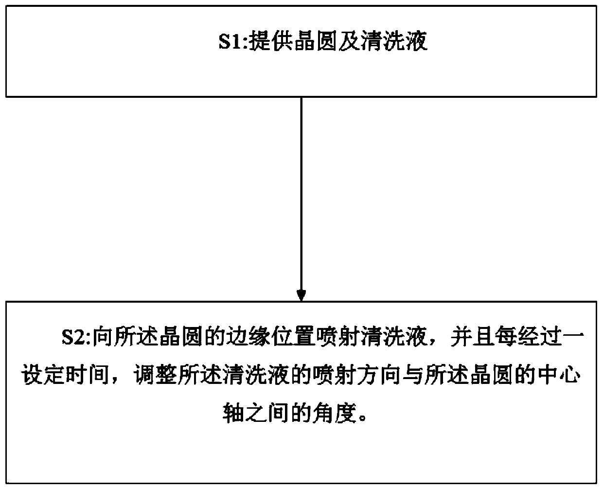
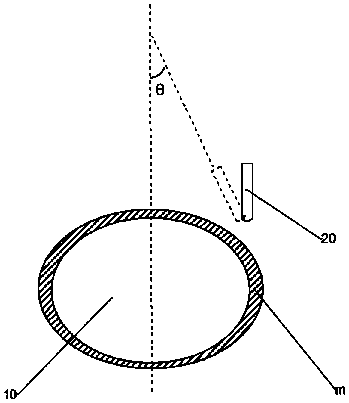
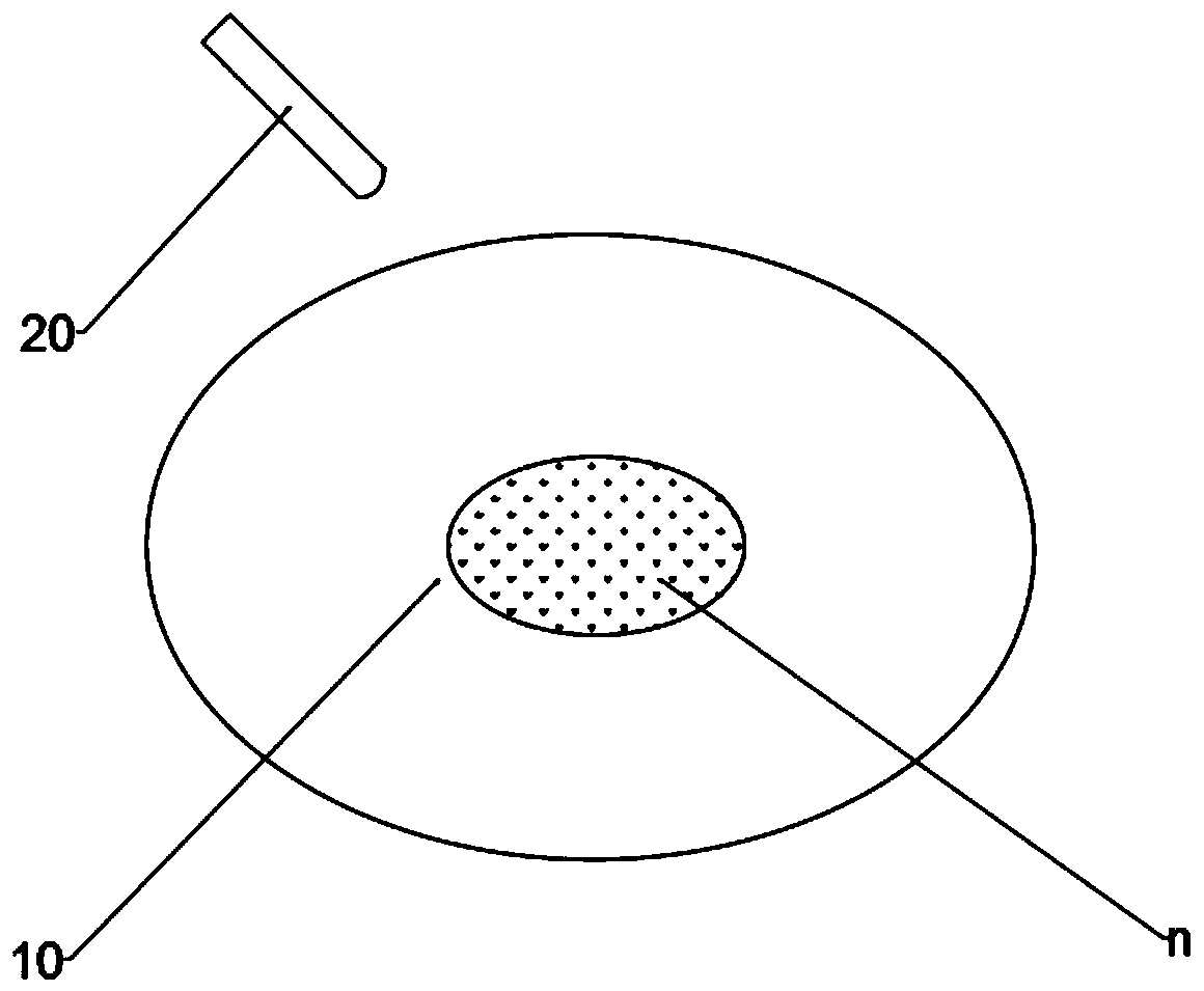
[0026] Such as figure 1 and figure 2 As shown, the present embodiment provides a wafer cleaning method, comprising:

[0027] S1: placing a wafer 10 on a turntable and rotating it;

[0028] S2: Spray cleaning liquid to the edge position m of the wafer, and adjust an angle θ between the spraying direction of the cleaning liquid and the central axis of the wafer every time a set time elapses. It should be noted that the edge position m is an annular area, and the maximum distance from any point in the annular a...


PUM


Abstract

The invention provides a wafer cleaning method, which comprises the following steps: placing a wafer on a rotary table and rotating the wafer; and spraying cleaning liquid to the edge position of thewafer, and adjusting the angle between the spraying direction of the cleaning liquid and the central axis of the wafer every set time. According to the invention, the cleaning solution is first sprayed to the central position of the wafer to enable pollutants such as particles in the center position of the wafer to move towards the edge position of the wafer, and then, the cleaning solution is sprayed to the edge position of the wafer and the angle between the spraying direction of the cleaning liquid and the central axis of the wafer is adjusted, so that multiple times of cleaning of the edgeposition of the wafer and fixed-point cleaning of the edge position of the wafer are achieved, the cleaning effect is better, and there are fewer particles and other pollutants on the surface of thewafer. By using the wafer cleaning method provided by the invention, the wafer edge cleaning capability can be enhanced, defects on the surface of the wafer can be reduced, and the yield of the wafercan be improved.

Description

technical field [0001] The invention relates to the technical field of semiconductor manufacturing, in particular to a wafer cleaning method. Background technique [0002] In the semiconductor manufacturing process, due to the higher and higher integration of semiconductor chips, the critical dimensions are getting smaller and smaller, and a clean and clean wafer surface is becoming more and more important for the manufacture of semiconductor devices. After the wafer preparation process is completed, the wafer needs to be cleaned. Since there are more particles and other pollutants on the edge of the wafer than in the center of the wafer, the cleaning of the wafer is mainly to remove the particles and other pollutants on the edge of the wafer. In the prior art, the equipment for cleaning wafers usually adopts a chip brushing machine. There are two common cleaning methods. One is to place the wafer on a rotating table and rotate it. The nano nozzle of the chip cleaning machin...

Claims


Application Information

Patent Timeline
Patent Type & Authority Applications(China)
IPC IPC(8): H01L21/02
CPCH01L21/02057
Inventor 孙兴
Owner SHANGHAI HUALI MICROELECTRONICS CORP
Learn More