
Safety discharging device and discharging system

A discharge device and discharge resistor technology, applied in circuit devices, emergency protection circuit devices, measurement devices, etc., can solve the problems of high equipment cost, inability to monitor the discharge effect of the discharge resistor, and failure of normal discharge of control systems and other components, achieving cost Low, flexible application and convenient effects

Active Publication Date: 2020-02-07
HUNAN CSR TIMES ELECTRIC VEHICLE
View PDF4 Cites 0 Cited by
  • Summary
  • Abstract
  • Description
  • Claims
  • Application Information

AI Technical Summary

Problems solved by technology

Among them, for the way of using the discharge resistor, the discharge effect of the discharge resistor cannot be monitored
For the active discharge method, equipment such as motor windings or braking resistors often requires complex control methods to control, which results in high equipment costs in the active method, and when the control system and other components fail Unable to discharge normally

Method used


Image

  • Safety discharging device and discharging system
  • Safety discharging device and discharging system
  • Safety discharging device and discharging system

Examples


Embodiment Construction

[0029] The implementation of the present invention will be described in detail below in conjunction with the accompanying drawings and examples, so as to fully understand and implement the process of how to apply technical means to solve technical problems and achieve technical effects in the present invention. It should be noted that, as long as there is no conflict, each embodiment and each feature in each embodiment of the present invention can be combined with each other, and the formed technical solutions are all within the protection scope of the present invention.

[0030] Also, in the following description, for purposes of explanation, numerous specific details are set forth in order to provide a thorough understanding of embodiments of the invention. It will be apparent, however, to one skilled in the art that the present invention may be practiced without the specific details or in the particular manner described.

[0031] After searching the patent literature, there...


PUM


Abstract

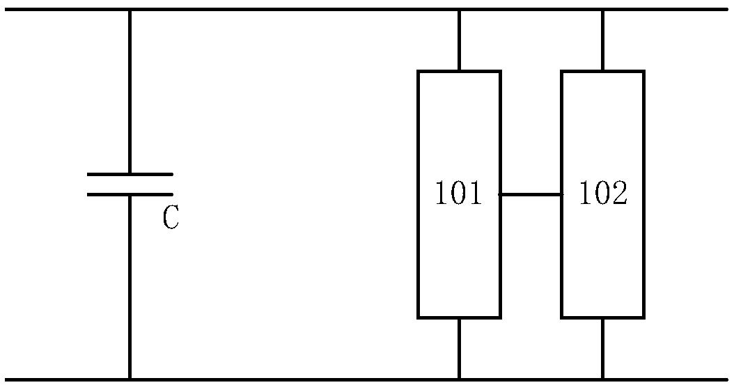
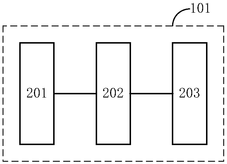
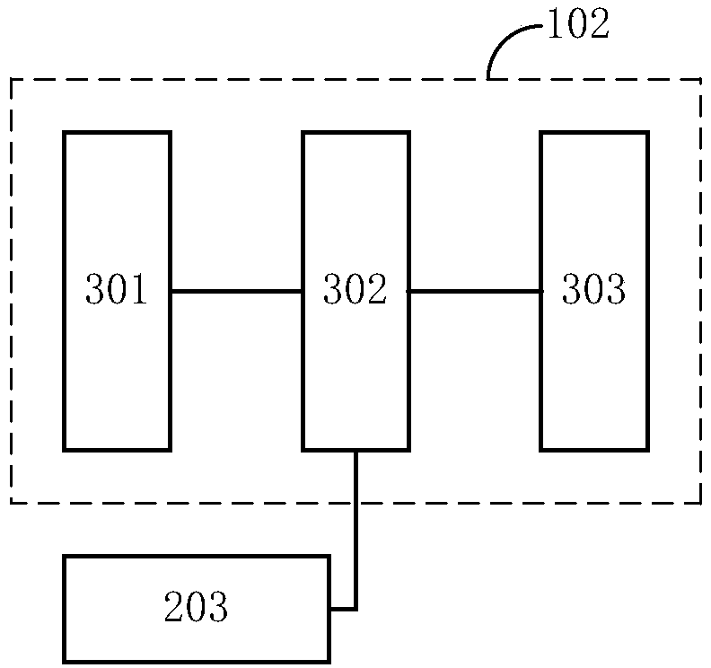
The invention relates to a safety discharging device. The safety discharging device comprises a discharging indication branch and a fault indication branch, wherein the discharging indication branch is connected to a discharging loop of an energy storage module and is used for consuming electric energy during the discharging process of the energy storage module and generating a corresponding discharging indication signal, and the fault indication branch is connected in parallel with the discharging indication branch and is used for determining whether a fault exists in the discharging indication branch or not and generating a corresponding fault indication signal when the fault occurs. In the safety discharging device provided by the invention, a discharging effect is displayed by additionally arranging a corresponding indication device, an open-circuit fault of a discharging resistor is indicated, so that the safety discharging process is achieved. By the device, whether high voltageexists in a discharging system or not can be indicated, whether the discharging system can normally discharge can be indicated, the energy touch module can be prevented from being in contact when a maintenance or test person finds out a relevant indication signal, so that the operation risk is reduced.

Description

technical field [0001] The invention relates to the technical field of inverters, in particular to a safe discharge device and a discharge system. Background technique [0002] For inverters, frequency converters and reactive power compensation devices, since most of their applications are high-voltage occasions, the internal capacitors are mostly high-voltage capacitors. The voltage at both ends of the high-voltage capacitor is often dangerous, especially during equipment maintenance or capacitor high-voltage testing, if the capacitor energy cannot be discharged immediately, it will easily cause harm to equipment maintenance personnel or testers. [0003] Traditional capacitive discharge solutions include two methods: passive discharge devices such as discharge resistors and active discharge devices such as cooling motor windings or braking resistors. Wherein, for the way of using the discharge resistor, the discharge effect of the discharge resistor cannot be monitored. ...

Claims


Application Information

Patent Timeline
Patent Type & Authority Applications(China)
IPC IPC(8): H02H9/04G01R31/00G01R31/54
CPCH02H9/04G01R31/00
Inventor 胡振球彭再武黄炫方尹志刚黄河
Owner HUNAN CSR TIMES ELECTRIC VEHICLE
Learn More