Charging and discharging control method and device and UPS system

A charge and discharge control, charge and discharge technology, applied in the direction of circuit devices, battery circuit devices, secondary battery charging/discharging, etc., can solve problems such as shortening the cycle life of single batteries, affecting the performance of battery packs, and lacking, to achieve reliable High performance, improved stability and reliability, and good stability

Active Publication Date: 2020-02-07
湖南小步科技有限公司
View PDF6 Cites 4 Cited by
  • Summary
  • Abstract
  • Description
  • Claims
  • Application Information

AI Technical Summary

Problems solved by technology

[0003] During the working process of the existing UPS system, when the battery pack has faults such as overcharging, over-discharging, large charging and discharging current, short circuit, etc., there is no effective control of the charging and discharging capacity and the free conversion of the UPS system between charging and discharging modes. A charging and discharging control strategy with good stability and high reliability will seriously affect the performance of the battery pack and shorten the cycle life of the single battery; therefore, how to control the charging and discharging of the UPS system to ensure that the UPS system can effectively control the battery pack It is a problem to be solved to improve the charging and discharging quality of the UPS system and improve the stability and reliability of the UPS system.

Method used


Image

  • Charging and discharging control method and device and UPS system
  • Charging and discharging control method and device and UPS system
  • Charging and discharging control method and device and UPS system

Examples


Embodiment Construction

[0036] The embodiments of the present invention will be described in detail below with reference to the accompanying drawings, but the present invention can be implemented in many different ways defined and covered by the claims.

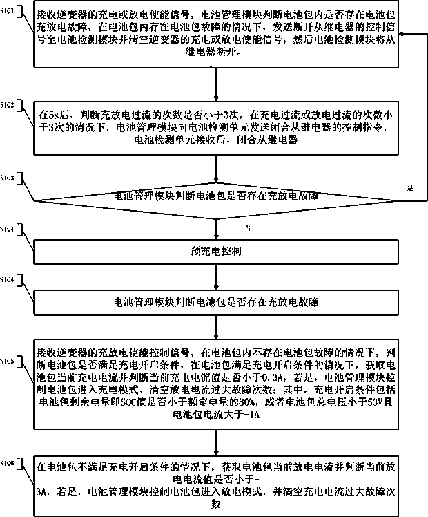
[0037] as attached figure 1 Shown, a kind of charging and discharging control method of UPS system, this method comprises the following steps:

[0038] S101: Receive the charging or discharging enable signal from the inverter, and the battery management module judges whether there is a battery pack charging and discharging fault in the battery pack, and if there is a battery pack fault in the battery pack, sends a control signal to disconnect the slave relay to The battery detection module will clear the charge or discharge enable signal of the inverter, and then the battery detection module will disconnect from the relay.

[0039] Among them, the battery pack failure includes one or more of battery pack overcurrent, single cell overvoltage, single...


PUM


Abstract

The invention provides a charging and discharging control method which comprises the following steps: a charging or discharging enable signal of an inverter is received, and a slave relay is disconnected under the condition that a battery pack fault exists in a battery pack; if the number of charging and discharging over-current times is less than L, a battery management module sends a control instruction for closing the slave relay to a battery detection unit and enters a pre-charging control flow; and if the battery pack meets a charging starting condition, whether the current charging current value is smaller than a first preset current value or not is judged. The invention further provides a charging and discharging control device and a UPS system. According to the invention, the charging and discharging of the battery pack can be controlled, switching between a charging mode and a discharging mode can be realized, and the situation in which the performance of the battery pack is influenced and the cyclic service life of a single battery is shortened due to charging and discharging under the condition that the battery pack has a fault can be avoided.

Description

technical field [0001] The invention relates to the technical field of uninterruptible power supplies, in particular to a charging and discharging control method, device and UPS system. Background technique [0002] UPS (Uninterruptible Power System / Uninterruptible Power Supply), that is, uninterruptible power supply, is a system device that connects the battery (lead-acid battery or lithium battery) with the host, and converts DC power into commercial power through a module circuit such as the host inverter. , which is mainly used to provide stable and uninterrupted power supply to a single computer, computer network system or other power electronic precision equipment. [0003] During the working process of the existing UPS system, when the battery pack has overcharge, overdischarge, large charge and discharge current, short circuit and other faults, there is no effective control of the charge and discharge and the UPS system can freely switch between charge and discharge ...

Claims


Application Information

Patent Timeline
Patent Type & Authority Applications(China)
IPC IPC(8): H02J7/00H01M10/44
CPCH02J7/0068H02J7/0031H01M10/441H01M10/446Y02E60/10
Inventor 龚政陈智李勇龙祖刚唐桂青戴祥顺
Owner 湖南小步科技有限公司
Why Eureka
Try Eureka