
Distributed microgrid system energy scheduling and communication method, equipment and storage medium

A technology of energy scheduling and communication methods, which is applied in distribution line transmission systems, transmission systems, wired transmission systems, etc., can solve problems such as operational difficulties, power grid system burdens, and cost increases, and achieve dispatching efficiency, accurate transmission, achieve maximum effect

Active Publication Date: 2022-02-18
XI AN JIAOTONG UNIV
View PDF13 Cites 0 Cited by
  • Summary
  • Abstract
  • Description
  • Claims
  • Application Information

AI Technical Summary

Problems solved by technology

[0004] The information sharing of the existing microgrid system is low, and the power generation status, battery storage capacity, and load status of a single user cannot be fully fed back in time, resulting in low energy utilization in the microgrid system and poor economic benefits for users
In addition, due to the strong randomness of users in the construction of the micro-grid system, the traditional optical cable communication method needs to lay cables separately, which is difficult to operate and expensive, which restricts the construction of the micro-grid system and the optimization of system quality.
[0005] The traditional micro-grid structure requires each user in the system to be connected to the central router, and the central energy router performs distribution and energy scheduling. This structure has advantages for the optimization of communication and energy in the system, but in the actual environment, the power line Structure construction, new users do not choose the nearest grid bus but connect to the central controller, which will bring a huge burden to the grid system and greatly increase the cost

Method used


Image

  • Distributed microgrid system energy scheduling and communication method, equipment and storage medium
  • Distributed microgrid system energy scheduling and communication method, equipment and storage medium
  • Distributed microgrid system energy scheduling and communication method, equipment and storage medium

Examples


Embodiment Construction

[0049] In the description of the present invention, it should be noted that unless otherwise specified and limited, the terms "installation", "connection" and "connection" should be understood in a broad sense, for example, it can be a fixed connection or a detachable connection. Connected, or integrally connected; it can be mechanically connected or electrically connected; it can be directly connected or indirectly connected through an intermediary, and it can be the internal communication of two components. Those of ordinary skill in the art can understand the specific meanings of the above terms in the present invention in specific situations.

[0050] Various structural schematic diagrams according to the disclosed embodiments of the present invention are shown in the accompanying drawings. The figures are not drawn to scale, with certain details exaggerated and possibly omitted for clarity of presentation. The shapes of various regions and layers shown in the figure and ...


PUM


Abstract

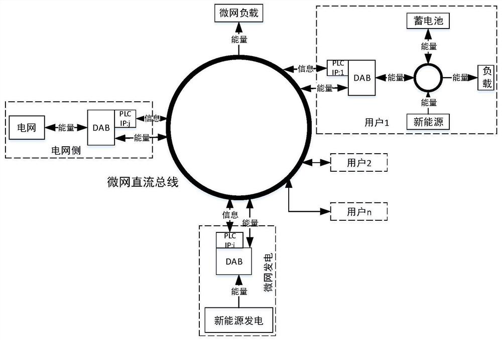
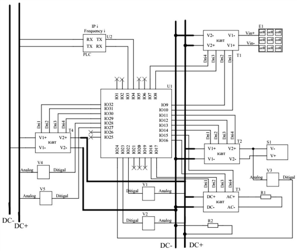
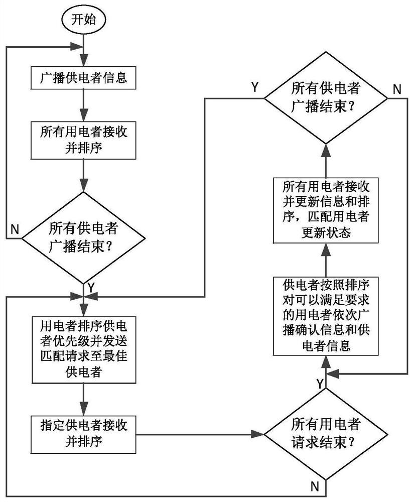
The invention discloses a distributed microgrid system energy scheduling and communication method, equipment and storage medium. Each single user accesses the microgrid system through an energy router and the energy router has a unique identification address; each single user according to the user's internal sensor Optimize the state of load, new energy generation and energy storage in the microgrid system and extract supply and demand requirements; the energy router performs signal flow interaction on the power line through the power line carrier communication PLC; adopts multi-agent control mode, each energy router is established according to The rules of supply and demand are sorted, matched, and energy dispatched; the power line carrier communication PLC converts the frequency to the frequency segments corresponding to different IPs according to the dispatching plan to realize signal flow communication. The invention realizes multi-host parallel communication and frequency hopping communication of the energy router based on the DC bus, can monitor the flow direction and magnitude of electric energy in real time, realizes the dynamic adjustment of the operating state of the module, and can also realize the metering and billing of the electric energy.

Description

technical field [0001] The invention belongs to the technical field of energy control scheduling and communication design in microgrids and smart grids, and in particular relates to a distributed microgrid system energy scheduling and communication method, equipment and storage medium. Background technique [0002] At present, the world is facing serious energy problems, and electric energy is being continuously developed and utilized as a clean energy source. Among them, the micro-grid system including small-capacity distributed new energy electric energy is widely researched and applied as an efficient, clean, economical and intelligent power supply system. As a bridge between the distribution network and distributed power, the microgrid system is a beneficial supplement to the large power grid. The system includes distributed power such as wind turbines, photovoltaic cells, fuel cells, micro gas turbines, etc., and can utilize a large number of distributed new energy. How...

Claims


Application Information

Patent Timeline
Patent Type & Authority Patents(China)
IPC IPC(8): H02J3/00H02J13/00H04B3/54
CPCH02J3/00H02J13/00007H04B3/544Y04S40/121Y04S40/128Y02E60/00
Inventor 张国钢潘廷哲唐舒建葛礼嘉耿英三王建华
Owner XI AN JIAOTONG UNIV
Learn More