Extruding machine capable of automatically discharging screw rod

An extruder and screw technology, which is applied in the field of extruders that can automatically discharge the screw, can solve the problems of time-consuming and labor-intensive extraction, template end face or template end face damage, molding material pollution, etc., and achieve the effect of saving manpower

Pending Publication Date: 2020-02-11
山东真诺智能设备有限公司
View PDF0 Cites 1 Cited by
  • Summary
  • Abstract
  • Description
  • Claims
  • Application Information

AI Technical Summary

Problems solved by technology

[0003] The following problems usually exist in the existing screw extruder: 1. The screw is the most important part in the screw extruder. The screw is usually arranged in the barrel, and the inner wall of the barrel and the screw jointly complete the extrusion of the material. Extrusion After the completion, the screw needs to be pulled out from the barrel for cleaning. Generally, the screw is pulled out of the barrel by manpower, especially when the viscosity of the material is high, the manual extraction is time-consuming and laborious, and it is difficult to pull out; 2. The screw extruder often Using a disc cutter as its cutting device, the rotation plane of the blade is parallel to the end face of the template. Usually the cutting device will rotate out or back with the random head. When the blade rotates back with the random head, because the distance between the blade and the template end face is relatively close When the blade and the end face of the template interfere with each other, that is, the blade will scratch the end face of the template or the end face of the template will damage the blade; 3. The initial molding material extruded by the screw extruder is generally waste material, and the waste material and the subsequent The normal molding materials are separated. In the prior art, the discharge hopper is generally used for manual separation, but some waste materials will adhere to the discharge hopper, thereby polluting the subsequent molding materials; 4. The materials sometimes contain Magnetic substance, the screw extruder in the prior art is not designed to remove the structure of the magnetic substance

Method used


Image

  • Extruding machine capable of automatically discharging screw rod
  • Extruding machine capable of automatically discharging screw rod
  • Extruding machine capable of automatically discharging screw rod

Examples


Embodiment 1

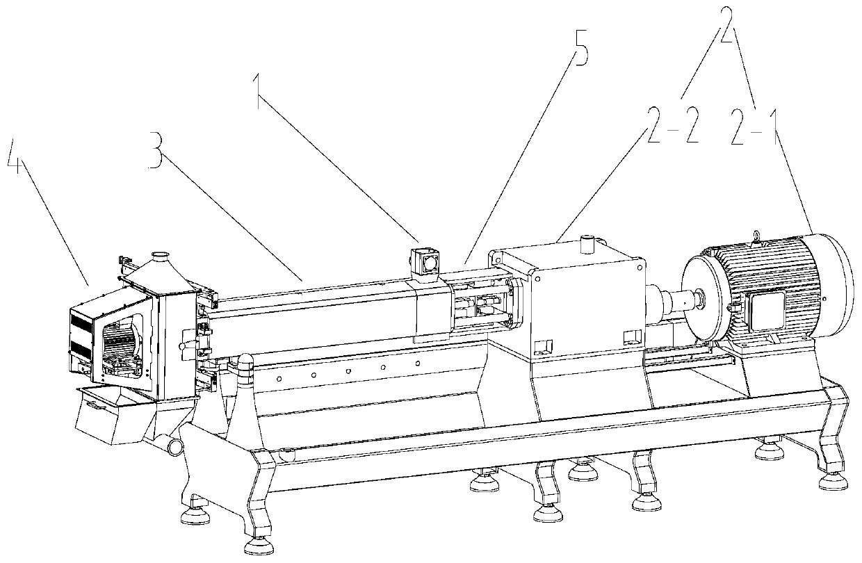
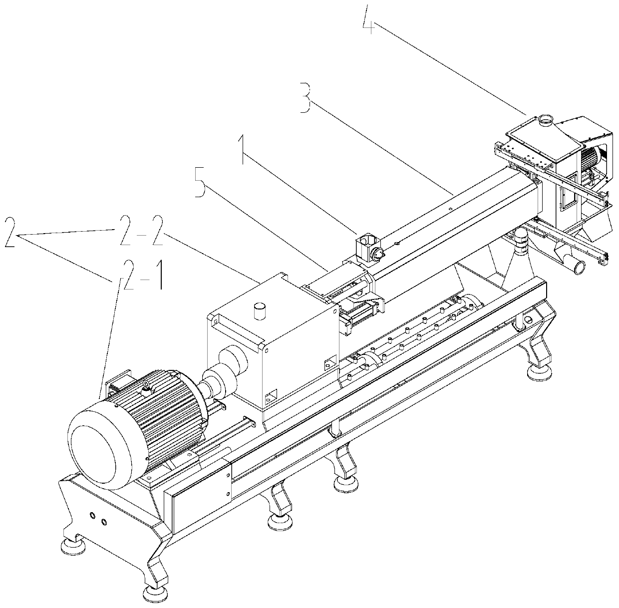
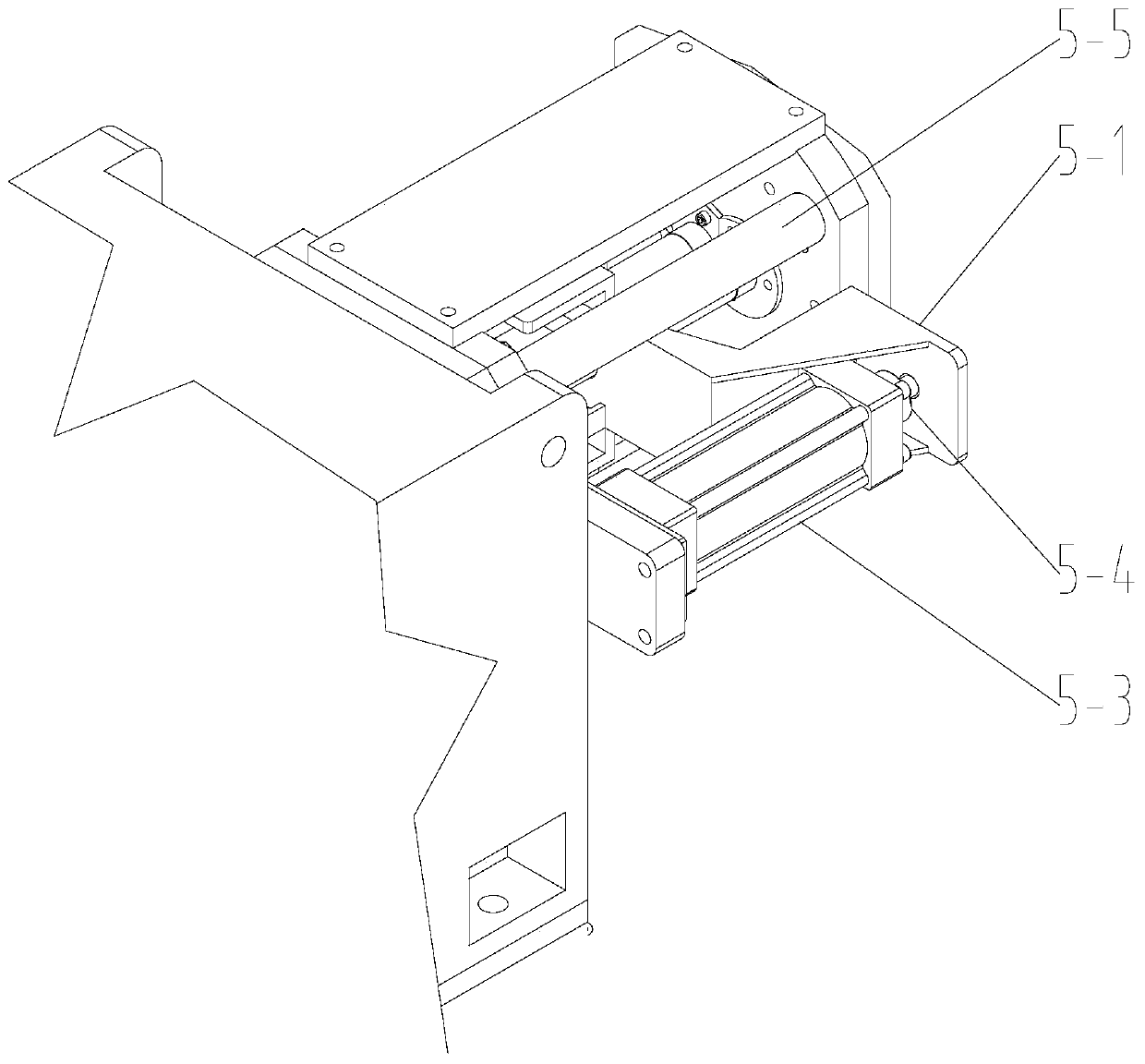
[0036] like Figure 1-4 As shown, this embodiment exemplifies an extruder that can automatically discharge the screw, including a feeding system 1, an extrusion system 3 and a discharge system 4 that are connected in sequence, and also includes a transmission system 2 that drives the extrusion system 3. The system 2 includes a motor 2-1 and a gearbox 2-2, the extrusion system 3 includes a barrel 3-2 and a screw 3-1 passing through the barrel 3-2, and the end of the screw 3-1 is connected to the gearbox 2- 2 are connected, between the gearbox 2-2 and the barrel 3-2, a screw ejection mechanism 5 is provided, and the screw ejection mechanism 5 is used to push the screw 3-1 out of the barrel 3-2.

[0037] The transmission system drives the screw to rotate, and the screws and the screw and the barrel interact together to extrude the material. After the extrusion is completed, the discharge system is generally unscrewed, and then the screw is pulled out from the barrel. The existing...

Embodiment 2

[0047] like Figure 5 As shown, the technical features of this embodiment that are the same as those of this embodiment will not be described in detail, and the technical features of this embodiment that are different from those of Embodiment 1 are:

[0048] The discharge system 4 includes a machine head 4-1;

[0049] Both sides of the end of machine barrel 3-2 are provided with the second guide rail 2-3 that extends to the outside, and the second guide rail 2-3 is arranged obliquely, and the machine head 4-1 is provided with and cooperates with the second guide rail 2-3. Slider 4-3.

[0050] After the extruder stops working, the screw rod of the extruder needs to be cleaned, and the discharge system needs to be separated from the barrel. The head of the extruder in the prior art moves along the guide rail to a direction away from the barrel. Then pull out the screw from the barrel, and return the machine head after cleaning the screw. The setting direction of the guide rai...

Embodiment 3

[0053] like Figure 6-7 As shown, the technical features of this embodiment that are the same as those of Embodiment 1-2 will not be repeated, and the technical features of this embodiment that are different from those of Embodiment 1-2 are:

[0054] The discharge system 4 includes a head 4-1 and a hopper 4-2, the head 4-1 is provided with an outlet, and the hopper 4-2 is arranged at the outlet of the head 4-1;

[0055] The discharge system 4 also includes a waste hopper 4-4 arranged side by side with the discharge hopper 4-2.

[0056] The edges of the discharge hopper 4-2 and the waste hopper 4-4 are provided with a clamping plate 4-5, and the machine head 4-1 is provided with a clamping groove 4-6 for the sliding of the clamping plate 4-5.

[0057] Extruders in the prior art are only provided with a discharge hopper, and no matter the waste material generated at the beginning or the material that needs to be collected after extruding, all need to be collected from the disch...


PUM


Abstract

The present invention relates to the technical field of extruding machines and particularly to an extruding machine capable of automatically discharging a screw rod. The extruding machine capable of automatically discharging the screw rod comprises a feeding system, an extruding system and a discharging system in a successive connection, and also comprises a transmission system for driving the extruding system; the transmission system comprises a motor and a gearbox, the extruding system comprises a machine barrel and a screw rod penetrating through the machine barrel, an end part of the screwrod is connected with the gearbox, a screw rod push-out mechanism is arranged between the gearbox and the machine barrel, and the screw rod push-out mechanism is used for pushing the screw rod out ofthe machine barrel. In the extruding machine capable of automatically discharging the screw rod, the screw rod push-out mechanism can push the screw rod out of the machine barrel, is reasonable in design, saves time and effort, also conducts improvement of the whole device, is optimized in structure and well solves problems existing in the prior art.

Description

technical field [0001] The invention relates to the technical field of extruders, in particular to an extruder capable of automatically extruding a screw. Background technique [0002] Screw extruder is widely used in food processing such as cereal food, snack food, nutritional rice flour, tissue protein, rice reconstitution, starch gelatinization, caramel products, pet food, aquatic feed, etc. Cutting force, frictional force, heating and other effects can realize the processing of solid food materials such as crushing, kneading, mixing, aging, sterilization, pre-drying, forming, etc. The screw extruder can produce puffed, textured or other shaped products. [0003] The following problems usually exist in the existing screw extruder: 1. The screw is the most important part in the screw extruder. The screw is usually arranged in the barrel, and the inner wall of the barrel and the screw jointly complete the extrusion of the material. Extrusion After the completion, the screw...

Claims


Application Information

Patent Timeline
Patent Type & Authority Applications(China)
IPC IPC(8): A23N17/00A23P30/20B03C1/02
CPCA23N17/005A23P30/20B03C1/02
Inventor 安敬强高飞孟祥华
Owner 山东真诺智能设备有限公司
Why Eureka
Try Eureka