Welding device for industrial machinery production

A welding device and industrial machinery technology, applied in auxiliary devices, welding equipment, welding equipment, etc., can solve the problems of difficulty in meeting large-scale round pipe welding, fixing round pipes of various sizes and specifications, and low work efficiency of workers. Improve fixing efficiency, reduce workload, and avoid the effect of insufficient fit

Inactive Publication Date: 2020-02-11
郭和俊
View PDF10 Cites 9 Cited by
  • Summary
  • Abstract
  • Description
  • Claims
  • Application Information

AI Technical Summary

Problems solved by technology

[0003] During the welding process, the round pipe needs to be rotated according to the welding progress. The work efficiency of the workers is low, the work intensity is high, and it is difficult to meet the welding of large quantities of round pipes. The existing round pipe welding device has a complex structure and troublesome operation. During the welding process of round pipes, it is difficult for the round pipe placement mechanism to fix round pipes of various sizes and specifications, so there is an urgent need for a welding device for industrial machinery production to solve the above problems

Method used


Image

  • Welding device for industrial machinery production
  • Welding device for industrial machinery production
  • Welding device for industrial machinery production

Examples


Embodiment 1

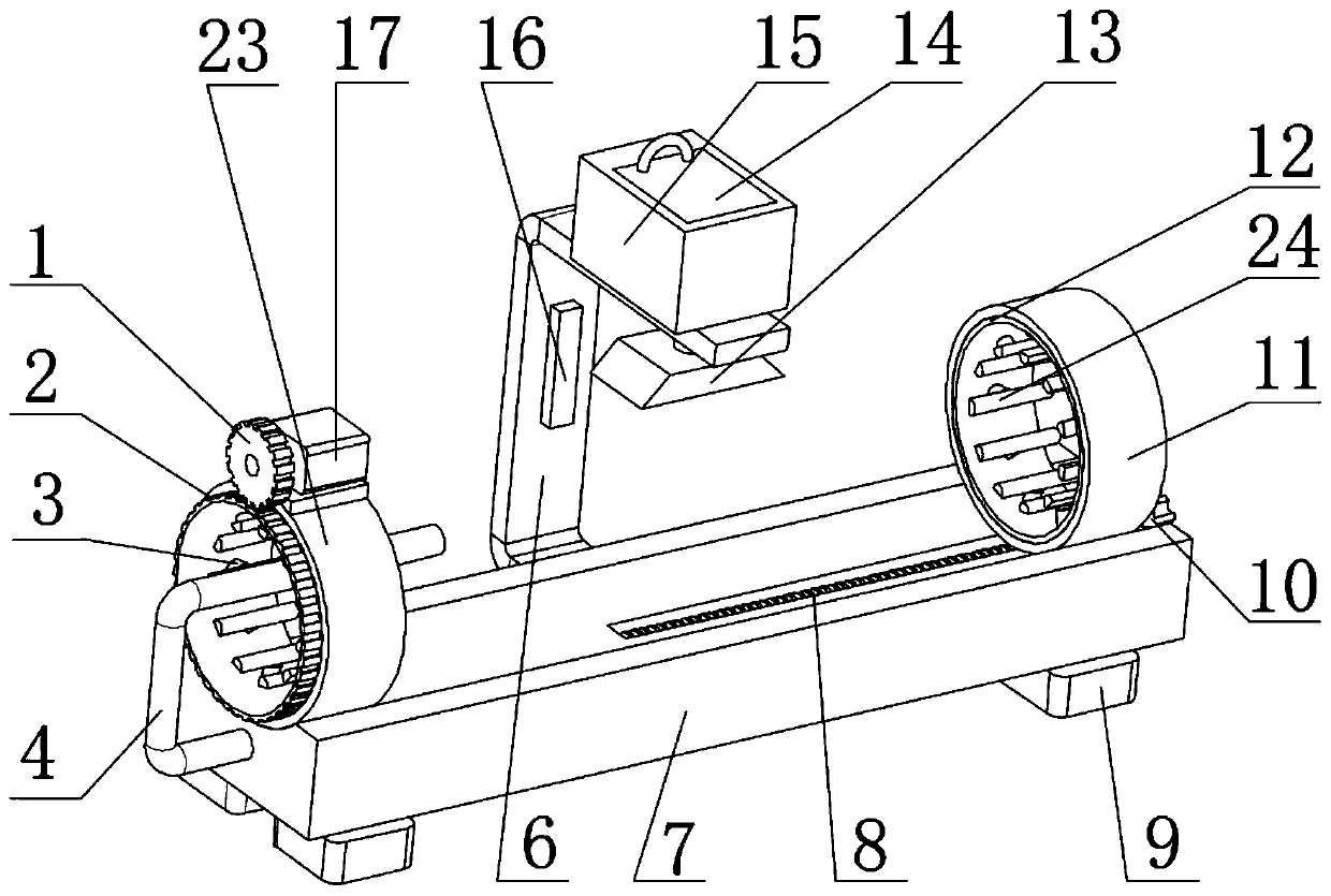
[0026] refer to Figure 1-3 , a welding device for industrial machinery production, comprising a base 7, an arc-shaped groove is provided on the top outer wall of the base 7, and a first ring 23 is installed on one side of the top outer wall of the arc-shaped groove, and the inner wall of the first ring 23 is rotatably connected with a second A fixed ring 2, and one side of the outer wall of the first fixed ring 2 is provided with tooth grooves, the outer wall of the top of the first ring 23 is equipped with a fixed plate, and the outer wall of the top of the fixed plate is equipped with a motor 17, and the outer wall of the output shaft of the motor 17 is socketed There is a gear 1, and the gear 1 meshes with the tooth grooves on the first fixed ring 2. A connecting rod 4 is installed on the outer wall of one side of the base 7, and the other end of the connecting rod 4 extends into the first fixed ring 2.

[0027] In the present invention, the four corners of the bottom oute...

Embodiment 2

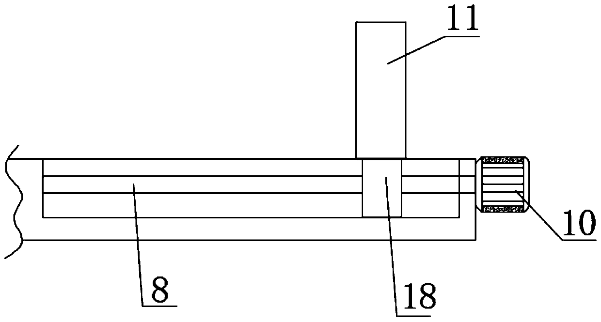
[0030] refer to Figure 1-4 , a welding device for industrial machinery production, which also includes a pressure sensor 22 installed on the top and bottom of the outer wall on one side of the second ring 11, and the same connecting ring 25 is installed on the outer wall on one side of the two pressure sensors 22.


PUM


Abstract

The invention discloses a welding device for industrial machinery production. The welding device comprises a base; an arc groove is formed in the outer wall of the top of the base; a first ring is mounted on one side of the outer wall of the top of the arc groove; the inner wall of the first ring is rotationally connected with a first fixed ring; a tooth groove is formed in one side of the peripheral outer wall of the first fixed ring; a fixed plate is mounted on the outer wall of the top of the first ring; a motor is mounted on the outer wall of the top of the fixed plate; a gear sleeves theperipheral outer wall of an output shaft of the motor; and the gear is engaged with the tooth groove on the first fixed ring. In the welding device, through arrangement of a lead screw, a slide blockand a servo motor, a second ring can be driven to move, and two round pipes to be welded can be tightly bonded to achieve welding; and through arrangement of the motor, the gear and the tooth groove on the first fixed ring, the round pipes on the second fixed ring and the first fixed ring can be driven to rotate for total welding of the peripheral outer walls thereof, so that the working efficiency is improved.

Description

technical field [0001] The invention relates to the technical field of industrial machinery, in particular to a welding device for industrial machinery production. Background technique [0002] Welding is a manufacturing process and technology for joining metal or other thermoplastic materials by means of heating, high temperature or high pressure. According to the specific welding process, welding can be subdivided into gas welding, resistance welding, arc welding, induction welding and laser welding, etc. Special welding, round pipes are widely used in our production and life. Round pipes can be used in pipelines, thermal equipment, machinery industry, petroleum geological drilling, containers, chemical industry and special purposes. During the use of round pipes, round pipes need to be The two ends of the pipe are welded with flanges respectively, so that multiple round pipes can be connected by flanges, which can meet the needs of use. In the welding process of tradition...

Claims


Application Information

Patent Timeline
Patent Type & Authority Applications(China)
IPC IPC(8): B08B15/04B23K31/12B23K37/00B23K37/053
CPCB08B15/04B23K31/125B23K37/00B23K37/0533
Inventor 郭和俊
Owner 郭和俊
Why Eureka
Try Eureka