Supercharge Your Innovation With Domain-Expert AI Agents!

Steady-state magnetic field coupling laser wire filling narrow groove repairing device

A technology of laser wire filling and magnetic field coupling, which is applied in laser welding equipment, metal processing equipment, welding equipment, etc., can solve the problems of affecting performance, difficulty in application, easy residual inclusion of pores in the weld, etc., to simplify the repair process and reduce defects Quantity, simple effect of installation

Pending Publication Date: 2020-02-11
ZHEJIANG UNIV OF TECH
View PDF0 Cites 2 Cited by
  • Summary
  • Abstract
  • Description
  • Claims
  • Application Information

AI Technical Summary

Problems solved by technology

However, there are also some problems in laser wire-filled welding: for example, defects such as inclusion pores are easy to remain in the weld, which affects the performance after repair; the adjustment of pure laser process parameters cannot control the movement direction of the fluid inside the molten pool, so as to control the structure of the solidified layer and performance
The device disclosed in the above documents does not have a steady-state magnetic field for laser wire welding, and the magnetic field generated by the device acts on the entire substrate and cannot accurately act on the molten pool, and it is difficult to apply to parts with complex shapes such as shafts and curved surfaces.

Method used


Image

  • Steady-state magnetic field coupling laser wire filling narrow groove repairing device
  • Steady-state magnetic field coupling laser wire filling narrow groove repairing device
  • Steady-state magnetic field coupling laser wire filling narrow groove repairing device

Examples


Embodiment Construction

[0019] The specific embodiments of the present invention will be described in detail below with reference to the drawings.

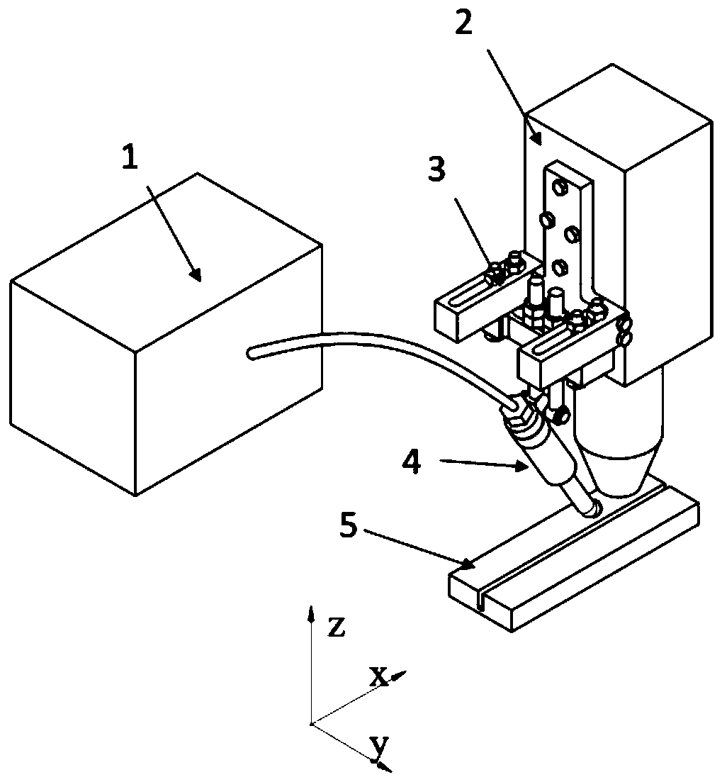
[0020] A steady-state magnetic field coupling laser wire filling narrow groove repair device includes a laser 2, a wire feeder 1, a wire feed head 4 and a clamp 3 for fixing the wire feed head and adjustable the position of the wire feed head.

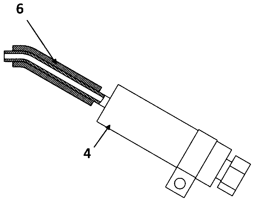
[0021] The wire feed head 4 is fixed on the laser 2 by a clamp 3, and an excitation coil 6 is provided outside the wire feed head 4, and a DC current is supplied to the excitation coil 6, so that a steady-state magnetic field is generated on the welding wire, and the steady-state magnetic field is accurately controlled by the welding wire. Sent into the molten pool area.

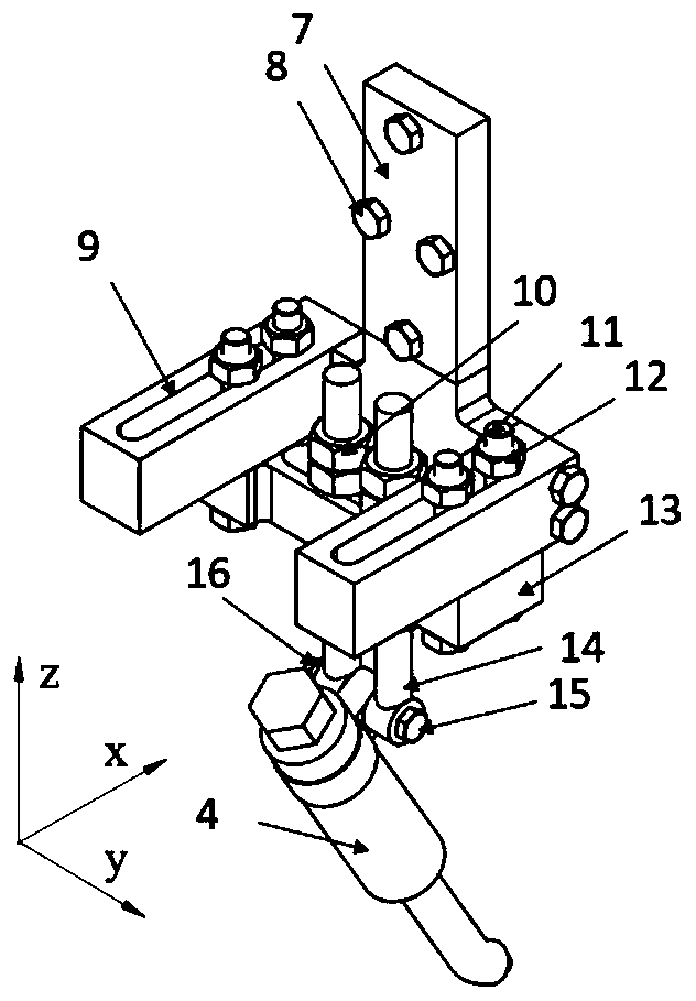
[0022] The clamp 3 includes a bottom plate 7 for fixing the clamp on the laser, a first adjustment plate 9 along the X axis direction, a second adjustment plate 13 along the Y axis direction, and a first stud 14 along the Z axis direction.

[0023] The...


PUM


Abstract

The invention discloses a steady-state magnetic field coupling laser wire filling narrow groove repairing device. The steady-state magnetic field coupling laser wire filling narrow groove repairing device comprises a laser device, a wire feeder, a wire feeding head and a clamp used for fixing the wire feeding head and adjusting the position of the wire feeding head, wherein the wire feeding head is fixed to the laser device through the clamp; a magnet exciting coil is arranged outside the wire feeding head; direct current is introduced into the magnet exciting coil, so that a steady-state magnetic field is generated on a welding wire, and the steady-state magnetic field is accurately fed into a molten pool area through the welding wire; and the wire feeding head is made of a non-ferromagnetic material, and the welding wire is made of a ferromagnetic material. According to the steady-state magnetic field coupling laser wire filling narrow groove repairing device, the magnet exciting coil is additionally arranged on the wire feeding head, the welding wire serves as an iron core, and therefore the steady-state magnetic field can accurately and stably act on the molten pool area, and the steady-state magnetic field coupling laser wire filling narrow groove repairing device can be suitable for parts in different shapes such as shafts and curved surfaces.

Description

Technical field [0001] The invention relates to a device for repairing a narrow groove with a stable magnetic field coupling laser wire filling Background technique [0002] Laser remanufacturing technology is a general term for technologies that use high-energy laser beams as energy sources to remanufacture waste parts. In order not to damage the matrix too much or repair internal cracks, a milling groove with a high aspect ratio is required to meet the repair performance requirements. Finally, the milling groove area is filled with metal of the same material or similar performance by laser remanufacturing technology. However, when metal powder is used as a filling material for repair, there will be defects such as difficulty in feeding the powder into the narrow groove, pores, melting and defects due to hollow powder and other reasons. The laser filler wire welding has small heat impact, small welding deformation and due to the use of welding wire, it has a certain degree of r...

Claims


Application Information

Patent Timeline
IPC IPC(8): B23K26/34B23K26/346B23K26/70B23K26/60B23P6/00
CPCB23K26/34B23K26/346B23K26/702B23K26/60B23P6/00
Inventor 王梁夏洪超姚建华
Owner ZHEJIANG UNIV OF TECH
Features
  • R&D
  • Intellectual Property
  • Life Sciences
  • Materials
  • Tech Scout
  • Unparalleled Data Quality
  • Higher Quality Content
  • 60% Fewer Hallucinations
Learn More