Marking machine two-dimensional code marking head and two-dimensional code marking method

A technology of marking machine and two-dimensional code, which is applied in the field of two-dimensional code marking head of marking machine and two-dimensional code marking, can solve the problems affecting the printing quality of two-dimensional code, vibration of marking head, etc. The effect of printing quality, large matching clearance and reducing manufacturing cost

Inactive Publication Date: 2020-02-11
GUIZHOU LIYANG INT MFG
View PDF11 Cites 2 Cited by
  • Summary
  • Abstract
  • Description
  • Claims
  • Application Information

AI Technical Summary

Problems solved by technology

In the machinery manufacturing industry, two-dimensional codes are also gradually used to identify various mechanical parts. The two-dimensional codes on these parts are mostly marked on the surface of the parts by a marking machine. When the marking machine is running, It is through the reciprocating motion of the marking head along the vertical direction to mark the corresponding two-dimensional code points on the surface of the component. Therefore, the assembly accuracy of the marking head structure often determines the quality of the two-dimensional code marked. The marking head on the existing marking machine is mostly the friction pair structure of the slider and the slide rail. If there is a large deviation in the manufacturing process of the slider and the slide rail, the marking head will vibrate during the marking process. , affecting the print quality of the QR code

Method used


Image

  • Marking machine two-dimensional code marking head and two-dimensional code marking method

Examples


Embodiment Construction

[0019] The technical solution of the present invention is further described below, but the scope of protection is not limited to the description.

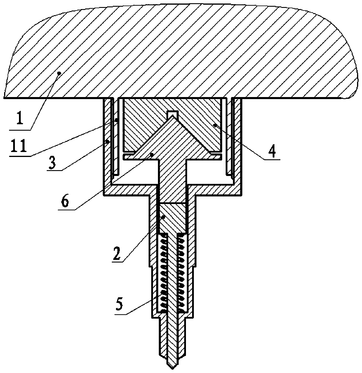
[0020] Such as figure 1 As shown, the present invention provides a two-dimensional code marking head of a marking machine, which includes a support seat 1, a marking needle 2, and a needle shell 3 hollow at both ends. A convex ring 11 is arranged on the support seat 1, and the convex ring 11 A high-frequency pulse electromagnet 4 is installed inside, and the marking needle 2 is connected with one end port of the needle shell 3 by sliding fit, and a spring 5 is also set on the marking needle, and the two ends of the spring 5 are connected with the marking needle 2 and the needle shell 3 respectively. The inner wall of the port is in contact, and the tail end of the marking needle 2 is also fixedly connected with a permanent magnet 6, and the other end port of the needle housing 3 is fixedly connected with the convex ring 11 through ...


PUM


Abstract

The invention provides a marking machine two-dimensional code marking head and a two-dimensional code marking method. The marking machine two-dimensional code marking head comprises a supporting seat,a marking needle and a needle shell. A protruding ring is arranged on the supporting seat. A high-frequency pulse electromagnet is installed in the protruding ring. The marking needle is connected with an end opening of one end of the needle shell in a sliding fit manner. The marking needle is further sleeved with a spring, and the two ends of the spring make contact with the inner wall of the marking needle and the inner wall of the end opening of the needle shell. The tail end of the marking needle is further fixedly connected with a permanent magnet. An end opening of the other end of theneedle shell is fixedly connected with the protruding ring through a threaded pair, and in addition, the permanent magnet and the high-frequency pulse electromagnet are oppositely arranged with opposite magnetic poles. The two-dimensional code marking method includes the step of using the marking head to print a two-dimensional code. By the adoption of the technical scheme, due to the cooperativeconnecting structure of the permanent magnet and the high-frequency pulse electromagnet, the code point marking consistency of the two-dimensional code is improved, the marking quality of the two-dimensional code is improved, and the requirement for the manufacturing precision of related composition structure parts of the marking head is lowered.

Description

technical field [0001] The invention belongs to the technical field of marking process devices, in particular to a two-dimensional code marking head of a marking machine and a two-dimensional code marking method. Background technique [0002] Two-dimensional code technology is a technology that uses a specific geometric figure to be distributed on a plane according to a certain rule. Black and white graphics record data symbol information. Since the two-dimensional code technology makes full use of the two-dimensional area on the plane, it greatly improves the The density of information makes it possible to encode large data on a small area. Secondly, because the two-dimensional code technology has super error correction capabilities, even if it is damaged in a large area, it can be accurately identified, making the two-dimensional code widely used in people's production. and every aspect of life. In the machinery manufacturing industry, two-dimensional codes are also gradu...

Claims


Application Information

Patent Timeline
Patent Type & Authority Applications(China)
IPC IPC(8): B41J3/01B41M3/14
CPCB41J3/01B41M3/14
Inventor 杨志伟严萍何明杭王正北李井平
Owner GUIZHOU LIYANG INT MFG
Why Eureka
Try Eureka