Marking film for surface of hard smooth substrate

A smooth substrate, hard technology, applied in the direction of copying/marking method, film/flake release coating, film/flake adhesive, etc., can solve glass, ceramic damage, poor performance, economical Good and other problems, to avoid damage, strong acid and alkali corrosion effect

Active Publication Date: 2020-02-11
JIAOZUO ZHUOLI STAMPING MATERIAL CO., LTD.
View PDF11 Cites 4 Cited by
  • Summary
  • Abstract
  • Description
  • Claims
  • Application Information

AI Technical Summary

Problems solved by technology

The former has poor bonding strength and resistance to complex conditions such as alcohol, sunlight, and acid-base corrosion, while the latter will cause damage to glass, ceramics, etc., and is not economical

Method used


Image

  • Marking film for surface of hard smooth substrate
  • Marking film for surface of hard smooth substrate
  • Marking film for surface of hard smooth substrate

Examples


Embodiment 1

[0030] A marking film for the surface of a hard and smooth substrate, which is made by the following method: use a thermal printer to heat the thermal transfer ribbon by means of pulse heating, so that the marking information is thermally transferred to the surface of the TPU film, and then heat and add pressure (temperature 140-150°C, pressure 1.3MPa-1.5MPa, heating time 5-8s) to melt the surface of the TPU film and bond it to the surface of the metal. After cooling, the marking film is obtained; the thermal transfer ribbon includes A tape base, the two sides of the tape base are respectively coated with a back coating layer and a heat transfer layer, and the heat transfer layer is sequentially composed of a protective layer and an adhesive layer from the inside to the outside of one side of the tape base;

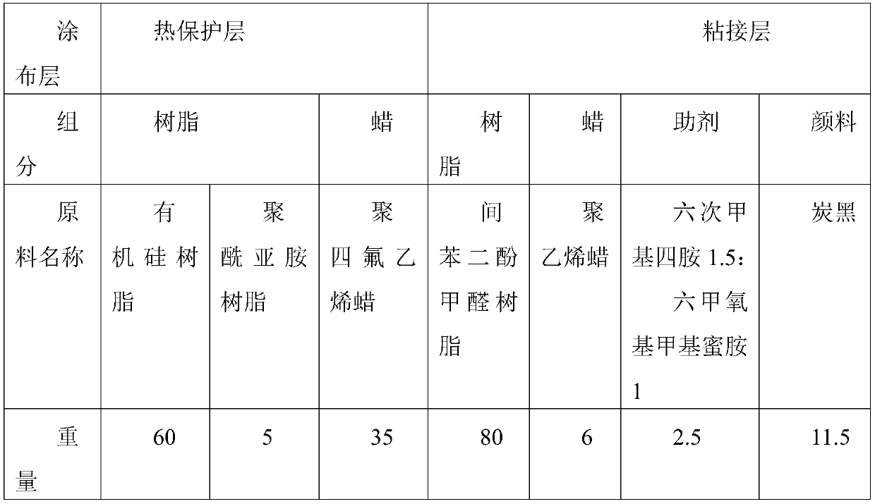
[0031] In this embodiment, the thermal transfer carbon ribbon is a high temperature resistant resin-based ribbon, which is prepared from the following raw materials:

[0...

Embodiment 2

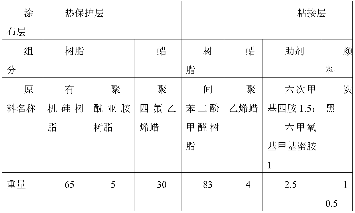
[0038] The difference between this embodiment and Example 1 is that the thermal transfer carbon ribbon is a high temperature resistant resin-based carbon ribbon with different raw material ratios and different coating thicknesses. High-temperature resin-based carbon ribbons are prepared from the following raw materials:

[0039]

[0040] When coating, the thickness of the back coat layer is 0.2 μm, the thickness of the protective layer is 1.0 μm, and the thickness of the adhesive layer is 1.3 μm.

Embodiment 3

[0042] The difference between this embodiment and Example 1 is that the thermal transfer carbon ribbon is a high temperature resistant resin-based carbon ribbon with different raw material ratios and different coating thicknesses. High-temperature resin-based carbon ribbons are prepared from the following raw materials:

[0043]

[0044]

[0045] When coating, the thickness of the back coat layer is 0.2 μm, the thickness of the protective layer is 1 μm, and the thickness of the adhesive layer is 1.4 μm.


PUM

PropertyMeasurementUnit
softening pointaaaaaaaaaa
thicknessaaaaaaaaaa
thicknessaaaaaaaaaa

Abstract

The invention aims at the limitation that a thermal transfer ribbon is difficult to apply to the surfaces of substrates such as metal in the prior art, and provides a marking film for the surface of ahard smooth substrate. A method for preparing the marking film comprises the following steps: printing marking information on the surface of a TPU thin film through heat transfer printing via a thermal transfer ribbon, then carrying out heating and pressurizing to enable the TPU thin film to be melted and to be bonded with the surface of metal, and carrying out cooling to obtain the marking film.The thermal transfer ribbon comprises a ribbon base, wherein the two sides of the ribbon base are coated with a back coating and a thermal transfer layer respectively, and the thermal transfer layeris sequentially composed of a protective layer and a bonding layer from inside to outside from the surface of one side of the ribbon base. The marking film can reach the bonding strength required in application, is good in corrosion resistance, and avoids damage caused by chemical etching.

Description

technical field [0001] The invention belongs to the technical field of thermal transfer materials, and in particular relates to a marking film for the surface of a hard and smooth substrate and a processing technology thereof. Background technique [0002] In recent years, with the development of thermal transfer printing technology, the use of carbon ribbon thermal transfer to replace traditional printing methods has become more and more widespread. However, the printing on the surface of metal and other materials is limited by the transfer method of carbon ribbons. After the tape is printed on the label, it is pasted, or it is chemically etched. The former has poor bonding strength and resistance to complex conditions such as alcohol, sunlight, and acid-base corrosion, while the latter will cause damage to glass, ceramics, etc., and is not economical. Contents of the invention [0003] The present invention aims at the limitation that the thermal transfer ribbon is diff...

Claims


Application Information

Patent Timeline
Patent Type & Authority Applications(China)
IPC IPC(8): C09J7/25C09J7/50C09J7/30C09D183/04C09D179/08C09D127/18C09J161/12C09J11/08C09J11/04B41M5/44
CPCB41M5/44B41M5/443B41M5/446C08L2201/08C08L2205/02C08L2205/03C09D183/04C09J11/04C09J11/08C09J161/12C09J2203/334C09J2427/003C09J2467/006C09J2479/083C09J2483/003C09J7/255C09J7/30C09J7/50C09J2301/122C09J2301/408C08L79/08C08L27/18C08L91/06C08L61/28C08K3/04
Inventor 李金洞杜小冬邓丽霞张乃凡牛杏梅王利红
Owner JIAOZUO ZHUOLI STAMPING MATERIAL CO., LTD.
Why Eureka
Try Eureka