
A drainage system for river bank and slope

A technology for drainage systems and slopes, applied in waterway systems, drainage structures, water supply devices, etc., can solve the problems of reduced vacuum in siphon pipes and difficult self-recovery of siphon effect, and achieve the effect of preventing silting

Active Publication Date: 2021-03-23
JIAXING JINXILAI TECH CO LTD
View PDF10 Cites 0 Cited by
  • Summary
  • Abstract
  • Description
  • Claims
  • Application Information

AI Technical Summary

Problems solved by technology

[0004] The invention aims at the defect that the siphon effect is suspended due to the drop of the groundwater level when the siphon drainage method is used in the prior art to drain the river bank slope, the vacuum degree in the siphon tube is reduced, and the siphon effect is difficult to recover by itself.

Method used


Image

  • A drainage system for river bank and slope
  • A drainage system for river bank and slope
  • A drainage system for river bank and slope

Examples


Embodiment 1

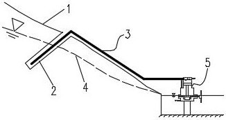
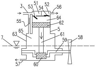
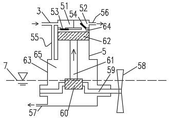
[0030] Such as Figure 1-4 Shown, a kind of drainage system of river bank slope comprises borehole 2, siphon pipe 3, starting device 5, drills the borehole 2 that forms downward slope at river bank slope 1, places siphon pipe 3 in borehole 2, and the inlet of siphon pipe 3 The water outlet is at the bottom of the borehole 2, the water outlet of the siphon tube 3 is connected to the starting device 5, the diameter of the siphon tube 3 is 4 mm, the starting device 5 is placed in the river water, the starting device 5 is fixed to the bottom of the river bed, and the starting device 5 includes a water inlet chamber 51 , outlet chamber 52, valve A 53, valve B 54, outlet pipe A55, outlet pipe B 56, outlet pipe C 57, paddle 58, rotating shaft 59, runner 60, connecting rod 61, plug body 62, shell 63, upper The chamber 64, the lower chamber 65, the siphon pipe 3 is connected to the water inlet chamber 51, the outlet pipe A 55 is connected between the siphon pipe 3 and the lower chamber...


PUM


Abstract

The invention provides a river bank slope drainage system, which is formed by drilling a downhill borehole on the river bank slope, and a drainage pipe is placed in the borehole. The water inlet is at the bottom of the borehole, and the water outlet is connected with the starting device. The starting device is placed in the river water, the starting device is fixed to the bottom of the river bed, the drain pipe is connected to the water inlet chamber, the outlet pipe A is connected between the drain pipe and the lower chamber, and the valve A is set between the upper chamber and the water inlet chamber Between, the valve B is set between the upper chamber and the water outlet chamber, the outlet pipe B is connected to the water outlet chamber, the outlet pipe C is connected to the bottom of the lower chamber, the elevation of the outlet pipe C is set below the lowest water level of the river, and the shaft is installed In the lower chamber, the rotating shaft is concave, one end of the rotating shaft is connected with the casing, the other end of the rotating shaft extends out of the casing and is connected with the paddle, the rotating wheel is arranged on the rotating shaft, and the connecting rod is connected between the rotating wheel and the plug body. The upper and lower chambers are separated by a plug body.

Description

technical field [0001] The invention belongs to the field of geotechnical engineering, in particular to a river bank slope drainage system and method. Background technique [0002] The construction of railways is often affected by the lines, and many tunnels have to be passed through. Tunnel construction will generate a large amount of spoil. The usual practice in engineering is to set up the surrounding tunnels according to the terrain. However, many mountain railways are located in high mountains and valleys, which are affected by the terrain. Tunnel spoils are often accumulated on the floodplain, and a large amount of spoils will form a high and steep slope. Due to the relatively loose soil, the stability of the high and steep slope is severely tested. At the same time, the railway built along the river will form a long embankment slope, and the stability of the embankment slope is crucial to the safety of trains. However, the occurrence of most landslides has a great co...

Claims


Application Information

Patent Timeline
Patent Type & Authority Patents(China)
IPC IPC(8): E03F5/00
CPCE03F5/00
Inventor 吕燕吕金坤
Owner JIAXING JINXILAI TECH CO LTD
Learn More