Flight test route planning method for measuring and controlling equipment precision identification

A technology of measurement and control equipment and precision, applied in the field of aerospace measurement and control, can solve problems such as flight route deviation, affecting the identification accuracy of field measurement and control equipment, etc., to achieve the effect of covering a wide range, improving test accuracy, and shortening the gap

Active Publication Date: 2020-02-11
中国人民解放军63660部队
View PDF11 Cites 3 Cited by
  • Summary
  • Abstract
  • Description
  • Claims
  • Application Information

AI Technical Summary

Problems solved by technology

[0005] The purpose of the present invention is to solve the technical problem that the flight route deviates from the actual situation caused by the inaccurate coordinate positioning ...

Method used


Image

  • Flight test route planning method for measuring and controlling equipment precision identification
  • Flight test route planning method for measuring and controlling equipment precision identification
  • Flight test route planning method for measuring and controlling equipment precision identification

Examples


Embodiment 1

[0095] The method and implementation steps will be described in detail below in conjunction with a certain accuracy appraisal test plan. The time, equipment, aircraft and other relevant information in the implementation plan are all hypothetical parameters and have nothing to do with reality.

[0096] The test time is April 3, 2019. 3 sets of equipment participated in the assessment, including 2 sets of external testing equipment and 1 set of optical testing equipment. The serial numbers are P 1 ,P 2 ,P 3 , The actual numbering sequence corresponding to each device depends on the coordinates of the device. The aircraft maintains a constant speed and a straight line flight with a flight speed of 70m / s. On the route of the assessment section, the side area of ​​the aircraft facing the optical measurement equipment is about 4m 2 . All equipment is in the clockwise direction of the examination route.

[0097] The basic parameters of the device are as follows:

[0098] 1. The...

Embodiment approach

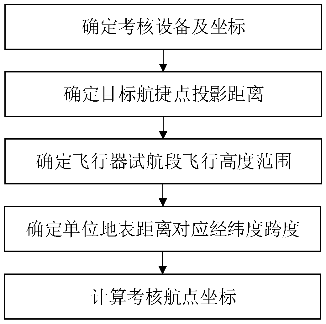
[0103] 1. Determine the coordinates of the assessment equipment

[0104] P 1 Device coordinates (117.4954°, 30.7291°, 867m).

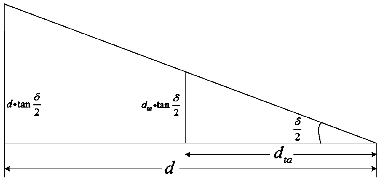
[0105] 2. Determine the distance to the target waypoint

[0106] According to equipment P 1 The azimuth velocity limit value ω max =10° / s, the waypoint of the target relative to the equipment can be obtained

[0107] Horizontal projection distance

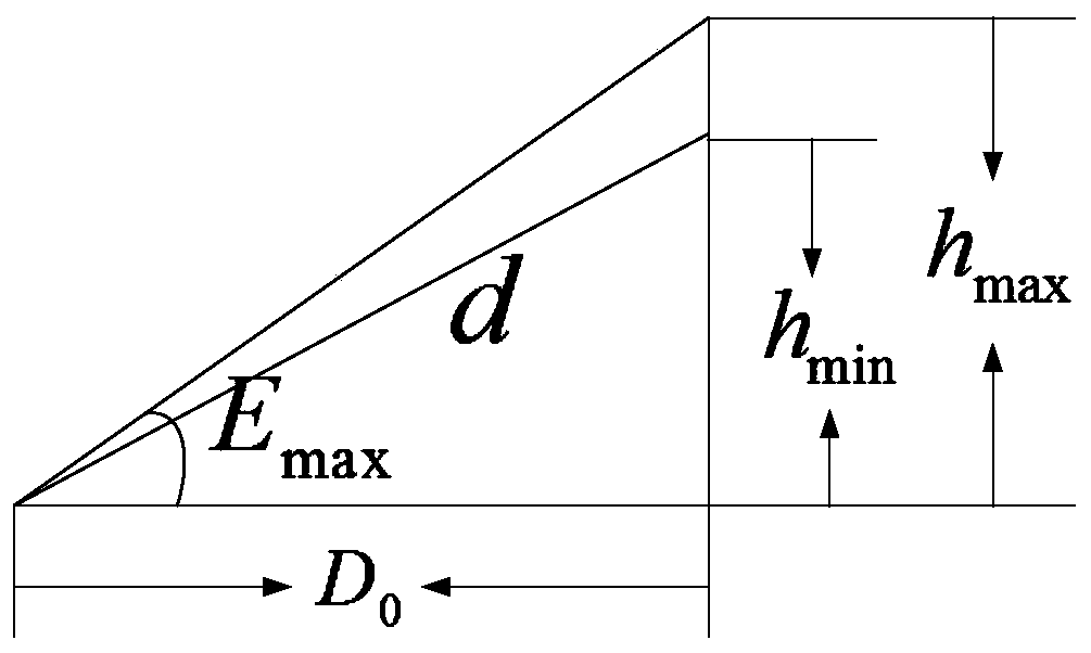
[0108] 3. Determine the distance to the fast point according to the limit of the shortest operating distance of the equipment, and then determine the minimum flight altitude of the assessment flight segment, and determine the maximum altitude according to the working range of the elevation angle with accuracy

[0109] Device P 1 The blind zone distance is 500m, so d 1 =500m.

[0110] Minimum flight altitude:

[0111] Maximum flight altitude: h max =D 0 gtan (E max )=401gtan (80°)=2274m.

[0112] Therefore, the flying height of the target in the examination section is h=2274m.

[0113] 4. D...

Embodiment 2

[0131] The accuracy appraisal test is now carried out on two external measurement equipment and one optical measurement equipment located in the field. According to the task requirements, the following implementation plan is formulated:

[0132] 1. Determine the coordinates of the assessment equipment

[0133] P 2 Equipment coordinates (117.4927°, 30.7262°, 867m), P 3 Device coordinates (117.4939°, 30.7292°, 867m). P 2 is the external test equipment, P 3 For photometric equipment.

[0134] 2. Determine the projection distance of the target navigation point of the assessment equipment

[0135] According to equipment P 2 The azimuth velocity limit value ω max =10° / s, the horizontal projection distance of the target relative to the device's navigation point can be obtained

[0136] According to equipment P 3 The azimuth velocity limit value ω max =15° / s, the horizontal projection distance of the target relative to the device's navigation point can be obtained

[01...


PUM


Abstract

The invention provides a flight test route planning method for measuring and controlling equipment precision identification. The method comprises the following specific steps: 1) determining assessment equipment and equipment coordinates, wherein one route can simultaneously assess one or two pieces of equipment; 2) determining a projection distance of a target endurance point; 3) determining a flight height range of an aircraft trial route segment according to the shortest acting distance of the equipment and the precision-guaranteed tracking pitch angle limit; 4) determining a longitude value and a latitude value span corresponding to the unit surface length according to the local latitude; and 5) determining the route direction and calculating the waypoint coordinates in combination with external conditions such as terrain, weather, low elevation, target RCS change and sun illumination included angle, and completing the flight route planning. The method provided by the invention isclosely combined with the longitude and latitude coordinates in a real map to set the flight route, thereby effectively improving the test efficiency and precision of the external field test equipment.

Description

technical field [0001] The invention belongs to the technical field of aerospace measurement and control, and specifically relates to an aircraft measurement and control system. Background technique [0002] The aircraft measurement and control system is an important subsystem of the range flight test. It is a huge and complex system, mainly composed of optical measurement, external measurement, remote measurement and remote control equipment and supporting software and hardware equipment. Positioning and monitoring, and at the same time complete important tasks such as measurement and acquisition of test data such as target flight test trajectory, scene, telemetry parameters, target characteristics, damage effects, etc., to provide data information for test identification, mission command, mission evaluation, etc. Various measurement and control equipment, as the most important part of range measurement and control, its measurement capability and measurement accuracy direct...

Claims


Application Information

Patent Timeline
IPC IPC(8): G01C21/00G01C21/20
CPCG01C21/005G01C21/20Y02A90/10
Inventor 曹锐顾祥龙杨耀东张智香胡亚雄王振坤张众森刘德超刘子敬
Owner 中国人民解放军63660部队
Why Eureka
Try Eureka