Broadband Injection Locked Frequency Multiplier
An injection locking and frequency multiplier technology, applied in power oscillators, electrical components, etc., to solve problems such as narrowing of the locking range
- Summary
- Abstract
- Description
- Claims
- Application Information
AI Technical Summary
Problems solved by technology
Method used
Image
Examples
Embodiment 1
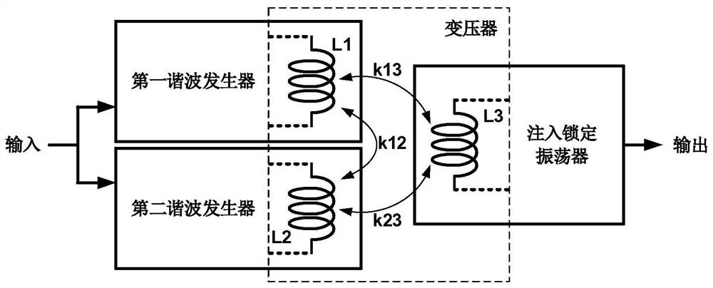
[0026] The embodiment of the present invention aims at the problem that the traditional injection-locked frequency multiplier has a wide locking range under high-power input, but the locking range will narrow rapidly when the input power decreases, and adopts a double-injection structure, such as figure 1 As shown, it includes the first and second harmonic generators and an injection-locked oscillator; the harmonic generator is used to generate nth harmonic signals (n=2, 3, 4...), and the injection-locked oscillator is used for Lock the harmonic signal generated by the harmonic generator; two harmonic generators and an injection-locked oscillator are connected through a transformer coupling composed of their own internal inductance; the two harmonic generators convert the input fundamental wave signal into The two harmonic signals are then respectively coupled to the injection-locked oscillator through a transformer to achieve frequency doubling.
[0027] The first harmonic ge...
Embodiment 2
[0029] The embodiment of the present invention increases the input buffer and the output buffer on the basis of the first embodiment, such as figure 2 As shown, two harmonic generators and an injection-locked oscillator form the core circuit of the broadband injection-locked frequency multiplier. The broadband injection-locked frequency multiplier includes a core circuit, an input buffer and an output buffer, the input buffer is connected to the input end of the core circuit, and the output buffer is connected to the output end of the core circuit; the above-mentioned connection mode can be direct coupling, transformer coupling or AC coupling.
Embodiment 3
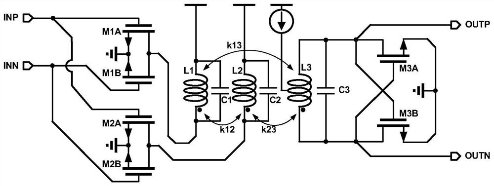
[0031] The broadband injection-locked frequency multiplier disclosed in the embodiment of the present invention is a broadband injection-locked frequency multiplier that can realize frequency doubling, and its circuit is as follows image 3 As shown, it contains two harmonic generators that generate the second harmonic and an injection-locked oscillator. The two harmonic generators include: common-source first transistor M1 and second transistor M2, common-source third transistor M3 and fourth transistor M4, first coupled inductor L1 and second coupled inductor L2, and first capacitor C1 and the second capacitor C2; the first transistor M1, the second transistor M2, the first coupled inductor L1, and the first capacitor C1 constitute the first harmonic generator, the third transistor M3, the fourth transistor M4, the second coupled inductor L2, The second capacitor C2 constitutes the second harmonic generator; the gate of the first transistor M1 is connected to the positive in...
PUM
 Abstract
Description
Claims
Application Information
 - R&D
- Intellectual Property
- Life Sciences
- Materials
- Tech Scout
- Unparalleled Data Quality
- Higher Quality Content
- 60% Fewer Hallucinations
Browse by: Latest US Patents, China's latest patents, Technical Efficacy Thesaurus, Application Domain, Technology Topic, Popular Technical Reports.
© 2025 PatSnap. All rights reserved.Legal|Privacy policy|Modern Slavery Act Transparency Statement|Sitemap|About US| Contact US: help@patsnap.com


